|
|
|
|
  - For the past two years, I’ve been planning to build myself a 3D printer from some old Inkjet printers that I had collected over the years. But not until two weeks ago had I actually started to work on it.
The 3D printer I want to made uses a ink jets to print a chemical onto a building platform. The building platform goes down as a new layer of powder is spread onto it. Then a chemical is sprayed from the print head that will cause powder to bind. If you want more information on these kinds of printers look here
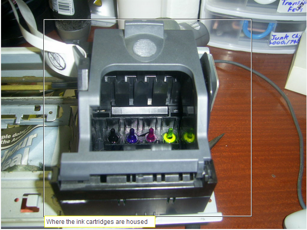
My printer of choice was an old Epson Stylus C63 for these reasons:
1. The ink cartridges only supply ink, they do not have ink jet nozzles themselves
2. I can attach rubber hoses or some other form of tubing that allows me to print another chemical of my choosing
3. The print head nozzles uses a piezoelectric material to produce droplets of ink (lasts much longer than thermal inkjets)
4. Most service manuals for Epson Printers come with a detailed schematic of the main board.
Note: Due to certain circumstances, this printer had already been pulled apart.
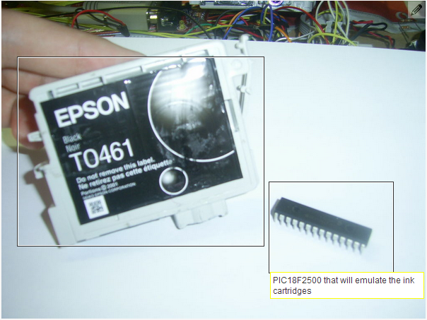
The first thing I needed to do was get my printer running so I could plug my logic analyser in and look at the signals, the problem was that I was missing one ink cartridge so the printer refused to print, or do anything.
Due to my budget (jobless and about to start university) I decided to try and Emulate the missing cartridge, or all of them using one microcontroller, thus allowing me to move forward and using water for the print head instead of ink that stains.
-
-
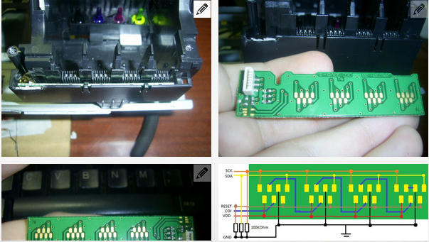
So in order to emulate the ink cartridges, I need to know how they work first. Luckily the ink cartridges in my printer have simple EEPROMs that hold the ink usage and other important information about the ink cartridge such as the expiration date, colour, serial number and so on.
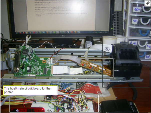
Inside the print head, there is a circuit board with pads mapped out that are an exact mirror of the pads on the ink cartridges and a ribbon cable that connects this board up to the main board on pins 1 to 6.
A quick look at the schematic for the main board reveals that pins 1 – 6 are named CVDD, CSDA, CRST, GND, CSCK and COI.
With these signal names I decided it would be best to draw out a schematic of the connecting board as it was not present in the service manual. This revealed that CSDA, CSCK, CRST have 100KOhm Pull-Down resistors, a bit unusual in my opinion as it’s not like I2C (uses Pull-Up Resistors typically 1.8KOhms to 47KOhms). The COI signal connects serially to the ink cartridges but on the end is shorted to GND. Curiously I tested the continuity of the pads on the ink cartridges and found that they are shorted, this means that when COI is grounded, all ink cartridges are present.
Now that I know the signal names, I wanted to see what the signals themselves looked like.
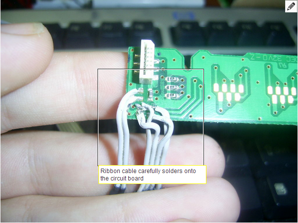
I got out my soldering iron, a ribbon cable (used to be an IDE cable from an old computer) and a craft knife. I cut 6 wire wide ribbon cable about 30cm long, stripped the ends carefully using the craft knife (a lot easier to use a craft knife to strip a ribbon cable than a pair of clippers or pliers), and soldered them onto the circuit board that mates with the ink cartridges.
I also stripped the other ends and soldered on some pins so I could plug them into my logic analyser.
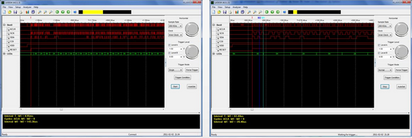
After plugging in the logic analyser into the circuit board and having a look at the signals, I found that immediately the SCK, SDA look nothing like I2C, I’m pretty sure that Epson must have invented their own serial protocol for talking to the EEPROMs inside the ink cartridges.
What I found is that CVDD gets powered up and shortly after, CRST and CSDA go up at the exact same time shortly followed by CSCK which pulses. CSDA changes on the Rising Edge of the CSCK and I’ll assume it gets read on the Falling Edge.
CSCK is Serial ClocK
CSDA is Serial Data
CRST is Reset
and CVDD is the power
Looks easy enough but I wanted more information about this protocol, were there any addresses being sent?
I turned up the sample rate on my logic analyser and found that there are 4 clock cycles, a pause, then 8 cycles, pause, 8 more and so on. The 4 clock cycles at the beginning gave me the idea that the first four could possibly be a 4 bit address of the ink cartridge. Still a lot of information was unknown about this protocol. So I did some research!
Googling around found nothing about this protocol, the next best place to look was in patents.
Yes, patents, I searched for "Epson SDA SCK RST memory eeprom" on http://www.freepatentsonline.com/ and one of the patents I found (US7660008 ) contained exactly what I was looking for. It outlined the SCK, SDA, RST and VDD of the protocol.
I’ll save you the hassle and point out what I found:
1. Flow chart diagrams describing what the Host and Slave does
2. A timing diagram of the protocol
3. The first 3 bits are a 3bit address followed by a Read/Write bit (Read = 0, Write = 1)
4. The address counter always starts at 0x00 and increments by 1 every clock cycle (This must mean it writes in bits, not bytes)
5. The moment RST goes low, the EEPROM stops everything and resets itself
6. There are 252 bits to read, the last 3 bits (actually they’re at the start) is the address of the ink cartridge.
Using what I had found, I decided to start writing code
What I wanted to do was read out the ROMs from the ink carts and then use those to try and emulate the missing ink cartridge I don’t have. This means creating a library that will act as a host to read the data but can also be used to emulate an ink cartridge.
Using previous knowledge from creating software based protocols, I created a header file with these functions:
• extern void epsnCartInit(void);
• extern void epsnCartStart(unsigned char addr, unsigned char write);
• extern void epsnCartStop(void);
• extern void epsnCartWrite(unsigned char data);
• extern unsigned char epsnCartRead(void);
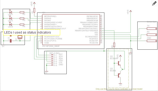
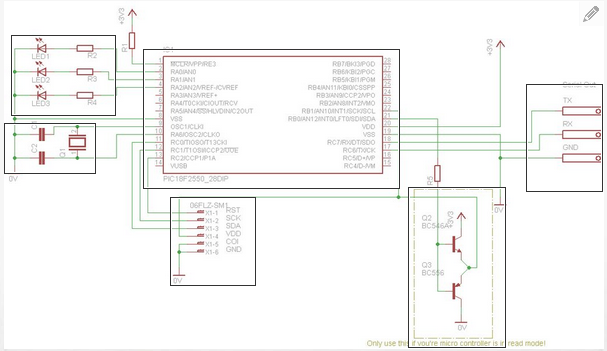
I also created the following definitions that help with remembering which pin was what:
For you microcontroller, you will need to modify these values to suit your application
#define _ecSCKTRIS TRISCbits.TRISC0
#define _ecSDATRIS TRISCbits.TRISC1
#define _ecRSTTRIS TRISCbits.TRISC2
#define _ecVDDTRIS TRISBbits.TRISB1
#define _ecSCKLat LATCbits.LATC0
#define _ecSDALat LATCbits.LATC1
#define _ecRSTLat LATCbits.LATC2
#define _ecVDDLat LATBbits.LATB0
#define _ecSCK PORTCbits.RC0
#define _ecSDA PORTCbits.RC1
#define _ecRST PORTCbits.RC2
#define _ecVDD PORTBbits.RB1
#define wait() DelayUS(50)
Note: I used a PIC18F and used Latches for setting the outputs, it’s just my preference in choice. You’re welcome to use any microcontroller you’re familiar with.
void epsnCartInit(){
_epsnCartSCKTRIS = 0;
_epsnCartSDATRIS = 0;
_epsnCartRSTTRIS = 0;
_epsnCartVDDTRIS = 0;
_epsnCartSCK = 0;
_epsnCartSDA = 0;
_epsnCartRST = 0;
_epsnCartVDD = 0;
_epsnCartSCKLat = 0;
_epsnCartSCKLat = 0;
_epsnCartSCKLat = 0;
_epsnCartSCKLat = 0;
}
The start function pulls VDD high, waits, then sets SDA according to the address bit as well as SCK. Waits, pulls SCK low, waits yet again and then pulls SDA high accordingly to the address. This repeats 2 more times except on the 4th time, SDA is set Low because we want to read the data in the EEPROMs not write.
void epsnCartStart(unsigned char addr,unsigned char write){
char i = 0; // Used for counting
char tmp = 0; // Temp storage variable
_ecVDDLat = 1; // Set VDD High
DelayMS(1); // Wait for the EEPROMs to get ready
_ecRSTLat = 1; // Enable the EEPROMs for communication
tmp = addr; // Copy the address into the temp variable
if(write){ // If we want to write
temp |= 0x08; //set the 4th bit high ( ‘|’ means OR )
}
while(i<4){
_ecSDALat = (tmp&0x01); // Set SDA High or Low according to the LSB
wait(); // Wait roughly 50uS
_ecSCKLat = 1; // Set Clock High
wait(); // Wait another 50uS
_ecSCKLat = 0; //Set Clock Low
wait(); // Wait another 50uS
tmp>>=1; //Right shift all the bits in tmp by one
i++; // increment the counter by one
}
}
The next function to implement is stop:
void epsnCartStop(){
_ecRSTLat = 0; //Set RST low
DelayMS(1); //Wait a bit
_ecVDDLat = 0; //Turn off the EEPROMS
}
And finally the read function:
unsigned char epsnCartRead(){
char i=0;
char temp = 0x00;
while(i<8){
temp>>=1; // Right shift the temp variable by one
_ecSCKLat = 1; //set SCK High
wait(); //Wait roughly 50uS
if(_ecSDA){ // If SDA is high
temp |= 0x80; // Then set bit 7 high
}
_ecSCKLat = 0; // Bring SCK low again
wait(); //wait another 50uS
i++; // Increment the counter by 1
}
return temp; // Return what we have read
}
We now have the basic functions that we need to read data from the ink cartridges, lets set up our microcontroller and set the results.
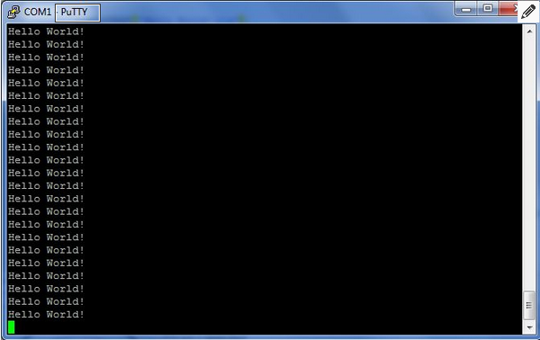
Start up your IDE, in my case it's MPLab, create a new project for your chip and create a basic hello world program to make sure your chip is going.
Note: My hello world program sends "Hello World!\r\n" over Serial to my computer at 38400bps
#include <p18f2550.h> // Include file specific for this chip
#include <usart.h> // USART Functions
#include <stdio.h> // printf(format,...) , sprintf(string, format, ...), etc...
#include "delay.h"
void main(){
PORTA = 0x00;
PORTB = 0x00;
PORTC = 0x00;
TRISA = 0x00;
TRISB = 0x00;
TRISC = 0x00;
ADCON1 = 0x0F; // This is such a trouble maker, never forget to turn the Analogue pins back to digital! :P
TRISCbits.TRISC7 = 1; // Turns the RX pin into an input (look it up in your datasheet for your chip)
OpenUSART(USART_TX_INT_OFF & USART_RX_INT_OFF & USART_ADDEN_OFF & USART_BRGH_HIGH & USART_CONT_RX & USART_EIGHT_BIT & USART_ASYNCH_MODE,78);
while(1){
putrsUSART("Hello World!\r\n"); // Send a message via Serial
LATAbits.LATA0 = ~LATAbits.LATA0; //Flash an LED by toggling it on and off
DelayMS(500); // A delay function I've created
}
}
This was set up with a 3.3V power supply because the ink cartridges run on 3.3Volts
Why a hello world program? Well, every time I set up a new project on a bread board, I always want to make sure I've got the configureation bits correct and that I'm not getting garbage in the terminal.
I think this is good practice and everyone should do it! :P
If your chip is doing something simple like mine, Great!! on to the next step
Implementing Our Library
Now we want to include the library we created for interfacing the microcontroller to the ink cartridge.
At the top of the file add:
#include "epsnCart.h" // the name of the header file we created earlier
Since this microcontroller is pretending to be the host, it's controlling the SCK, SDA and RST signals. so make sure they're outputs, add this with the other TRIS registers inside main():
epsnCartInit();
The next bit of code is what I used inside of the while(1) {
It requests an address starting at 0x00 then increments by one after 32 read bytes:
void main(){
char addr = 0, i = 0;
char string[40];
...
epsnCartInit(); // Initialised the pins used
while(1){ // Loop forever!
sprintf(string, "Reading cartridge with addr: 0x%02X\r\n",addr);
putsUSART(string); // prints a messge like: Reading cartridge with addr: 0x03
epsnCartStart(addr,0); // Start by sending the address in read mode
i = 0;
while(i<32){ // keep looping until i is no longer less than 32
sprintf(string,"0x%02X,",epsnCartRead());
putsUSART(string);
i++;
}
epsnCartStop(); //brings RST back low
putrsUSART("\r\n");
addr++
if(addr>7){
addr = 0;
}
DelayMS(500);
}
}
You're probably looking at the line "sprintf(string,"0x%02X,",epsnCartRead());" and going "Huh?"
sprintf is a string formatting function, much like printf except saves the formatted string into the variable string.
"0x%02X," will return a string with a readable hexadecimal value eg: 0xFE and epsnCartRead() returns a value that was read from the ink cart
This was set up with a 3.3V power supply because the ink cartridges run on 3.3Volts
I programmed this to my microcontroller, disconnected the print head from the printer to prevent interference.
I then plugged in the 3 ink cartridges I had and turned it on.
Note: At this point, if you ran this code for the first time, I would expect you have problems. Like me, I've gone over the code dozens of times, changing it here and there to make it work. It's normal if it doesn't work the first time for you. It's a great learning experience figuring out what went wrong! :P


-
phew, after all that hard work, it's alive!!!
Here is what I got of my terminal
Addr: 0x01
57,07,02,F2,00,00,00,00,00,50,98,6A,EB,D3,54,A3,39,50,14,15,31,93,E4,B4,24,96,57,04,35,F5,E4,14,
Addr: 0x02
00,00,00,00,00,00,00,00,00,00,00,00,00,00,00,00,00,00,00,00,00,00,00,00,00,00,00,00,00,00,00,00,
Addr: 0x03
03,00,02,F2,00,00,00,00,00,50,C8,1C,2A,A5,82,00,3B,50,16,17,31,93,E4,B4,24,96,57,04,35,F5,E4,34,
Addr: 0x04
00,00,00,00,00,00,00,00,00,00,00,00,00,00,00,00,00,00,00,00,00,00,00,00,00,00,00,00,00,00,00,00,
Addr: 0x05
00,00,00,00,00,00,00,00,00,00,00,00,00,00,00,00,00,00,00,00,00,00,00,00,00,00,00,00,00,00,00,00,
Addr: 0x06
00,00,00,00,00,00,00,00,00,00,00,00,00,00,00,00,00,00,00,00,00,00,00,00,00,00,00,00,00,00,00,00,
Addr: 0x07
03,00,02,F2,00,00,00,00,00,50,30,9F,74,81,D1,40,3B,50,1A,1B,31,93,E4,B4,24,96,57,04,35,F5,E4,74,
Now, see here how only the odd address returned data except 0x05?
That's because 0x05 is the address of the Magenta ink cartridge which I don't have sadly :(
-
Emulation Code Routines
Now the fun part!
I need the printer to think that there are four ink cartridges installed 聚焦离子束fib多少钱, to do this we need to implement some emulation functions first. Again from previous knowledge I have predefined these in the header:
• #define epsnCartReady() (_ecRST)
• extern unsigned char espnCartGetAddr(void);
• extern void epsnCartOut(unsigned char data);
• extern unsigned char epsnCartIn(unsigned char data);
epsnCartReady is a macro that is used check if the printer has RST set high.
epsnCartGetAddr returns the address that the print head is requesting.
epsnCartOut is used to send data to the Host controller
epsnCartIn is used to receive data from the Host when it’s writing
So this time, instead of controlling the SCK to go high or low, we need it to wait for it to go high or low, but if the reset goes low, then stop everything and return:
unsigned char espnCartGetAddr(void){
char i=0;
char temp = 0x00;
while((i<4) && _ecRST){ // Loop while i < 4 and RST is HIGH
temp>>=1; // Right Shift Temp by one
while((!_ecSCK) && (_ecRST)); // Wait for the clock to go high
if(_ecSDA){// only if SDA is high
temp |= 0x08; // then set the 4th bit
}
while((_ecSCK) && (_ecRST));// wait for the clock to go low
i++; // increment the counter
}
if(_ecRST == 0){
return 0xFF;//if RST went low, means the Host killed the signal
}
return temp; //return the address and the read/write bit
}
And the Out function:
void epsnCartOut(unsigned char data){
char i = 0;
char temp = data;
_ecSDATRIS = 0; // set the SDA to output
_ecSDALat = 0; // set SDA low
while((i<8) && _ecRST){ // Loop while I < 8 and RST is high
while(!_ecSCK && _ecRST); // Wait for SCK to go high
_ecSDALat = temp&0x01; // fib focused ion beam how much Set SDA high or low according to the first bit
while(_ecSCK && _ecRST); // Wait for SCK to go low
temp>>=1; // Right shift the data by one
i++; // increment the counter by one
}
_ecSDATRIS = 1; // Set SDA to an output
_ecSDA = 1; // not sure if this is needed
}
And finally the In function:
unsigned char epsnCartIn(void){
unsigned char i=0;
char temp = 0x00;
while((i<8) && _ecRST){ // Loop while I < 8 and RST is high
temp>>=1; // Right Shift the temp by one
while(!_ecSCK && _ecRST); // Wait for SCK to go High
if(_ecSDA){ //only id SDA is high
temp |= 0x80; // Set the 8th bit
}
while(_ecSCK && _ecRST);// Wait for SCK to go low
i++; // Increment the counter by one
}
return temp; // return what we have received
}
So what happens now is that we need to set up our microcontroller to contain the data we have dumped. Then allow the printer host to read and write to it.
Now the problem with this is that I don’t want my fake ink cartridges to ever get used up, so to do that is we have a fixed dump that the microcontroller will load into ram everytime it starts up. This will allow the printer to not only read, but write to it as well. When the microcontroller is powered off then back on, the previous data is restored. (Double Bonus)
Storing data arrays in the microcontroller, place this somewhere under the include, but before void main()
Note: This may vary between different microcontroller families, but it works nicely with my PIC18F
ram unsigned char black[32] = {0x10,0x00,0x02,0xF2,0x00,0x00,0x00,0x00,0x00,0x50,0x90,0x6A,0x17,0xE3,0x54,0xA3,
0x39,0x50,0x14,0x15,0x31,0x93,0xE4,0xB4,0x24,0x96,0x57,0x04,0x35,0xF5,0xE4,0x14};
ram unsigned char cyan[32] = {0x4C,0x04,0x01,0xF2,0x00,0x00,0x00,0x00,0x00,0x50,0x90,0x5A,0x19,0xF0,0x94,0x03,
0x3B,0x50,0x16,0x17,0x31,0x93,0xE4,0xB4,0x24,0x96,0x57,0x04,0x35,0xF5,0xE4,0x34};
ram unsigned char yellow[32] = {0x4A,0x04,0x01,0xF2,0x00,0x00,0x00,0x00,0x00,0x50,0x90,0x6A,0x8B,0xC9,0xA4,0x41,
0x3B,0x50,0x1A,0x1B,0x31,0x93,0xE4,0xB4,0x24,0x96,0x57,0x04,0x35,0xF5,0xE4,0x74};
Note: Noticed that I don’t have Magenta? That’s because that’s the ink cartridge I don’t have.
The next step is to write a routine that checks which ink cartridge is being requested, and allow the host to read and write to it.
This is how I did it:
void main(){
unsigned char* inkPtr;
char addr = 0x00;
...
While(1){
epsnCartStartListen();
while(epsnCartReady()==1); // Wait for the Ready signal to go back to low
while(epsnCartReady()==0);
addr = espnCartGetAddr();
if(addr&0x7 == 0x01){ // if the first 3 bits is equal to 0x01
inkPtr = &black[0]; // Point to the black data
}else if(addr&0x7 == 0x03){ // if the first 3 bits is equal to 0x03
inkPtr = &cyan[0]; // Point to the cyan data
}else if(addr[i]&0x7 == 0x05){
inkPtr = &cyan[0]; // This is meant to be Magenta, but I don’t have that
}else if(addr[i]&0x7 == 0x07){
inkPtr = &yellow[0];
}else{
continue: // Go back to the beginning of the main loop because we don't know this address
}
if(addr&0x08){//WriteMode – Check to see if the Host wants to write
while(epsnCartReady()){//keep looping until RST goes low
*inkPtr = epsnCartIn();
// the data the pointer is pointing to
// gets written with new data
inkPtr++; // Increment the Pointer
}
}else{//Read Mode
while(epsnCartReady()){
epsnCartOut(*inkPtr);
// Output the data the Pointer is pointing to
inkPtr++; // Inrement the pointer
}
}
}
}
Success!
After programming this new code and turning on my printer, the printer accepted 4 imaginary cartridges thanks to my microcontroller. I'm also quite shocked that I accepted the cyan ink cartridge data for magenta aswell!
This is a huge achievement for me as this is my first real world reverse engineering I’ve ever done and I got promising results.
Now I can continue with turning the printer into a 3D printer
I hope you guys liked this, this is my second instructable and this took me a while to write :P
- Mikatech Atmel printer mcu reverse engineer list:
- AT89xx whole series microcontroller crack: AT89C51 AT89C52 AT89S52 AT89S53 AT89S54 AT89S58 AT89S64 AT89C1051 AT89C2051 AT89C4051 AT89C55 AT89C55WD AT89C5131A AT89C51WD AT89C51ED2 AT89C51CC01 AT89S51 AT89C51CC02 AT89C51CC03 AT89C51RB2 AT89C51RC AT89C51RD2 AT89C51RD-CM AT89C51RC2 AT89C51ID2 AT87C5101 AT89C1051U AT89C2051X2 AT89C5130AM AT89C5130A AT89C5131AL AT89C5131AM AT89C51AC3 AT89C5132 AT89C51AC2 AT89C51CC03C AT89C51SND1C AT89C51CC03U AT89C51IC2 AT89C51RE2 AT89C51SND2 AT89LP2051 AT89LP2052 AT89LP213 AT89LP214 AT89LP216 AT89LP4051 AT89LP4052 AT89LP828 AT89LP428 AT89LS51 AT89LS52 AT89LV51 AT89LS53 AT89LS8252 AT89LV52 AT89LV55 AT89S2051 AT89S4051 AT89S8252 AT89S8253 ...
- AT90xx whole series microcontroller crack: AT90S1200 AT90S2323 AT90S2343 AT90S2331 AT90S4433 AT90S8515 AT90S8535 AT90S4414 AT90S4434 AT90S2313 90S1200 90S2323 90S2343 90S2331 90S4433 90S8515 90S8535 90S4414 90S4434 90S2313 ...
- AT90CAN/PWM/USB/xx whole series microcontroller read: AT90CAN32 AT90CAN64 AT90CAN128 AT90PWM2 AT90PWM216 AT90PWM2B AT90PWM3 AT90PWM316 AT90PWM3B AT90USB1286 AT90USB1287 AT90USB162 AT90USB646 AT90USB647 AT90USB82 ...
-
- AT91SAMxx whole series microcontroller firmware crack: AT91SAM9XE512 AT91SAM9XE256 AT91SAM9XE128 AT91SAM7S64B AT91SAM7S32B AT91SAM7SE512 AT91SAM7SE256 AT91SAM7SE32 AT91SAM7XC512 AT91SAM7XC256 AT91SAM7XC128 AT91SAM7X512 AT91SAM7X256 AT91SAM7X128 AT91SAM7S161 AT91SAM7S512 AT91SAM7S256 AT91SAM7S128 AT91SAM7S64 AT91SAM7S321 ...
- ATTinyxx whole series microcontroller firmware crack: ATtiny4 ATtiny5 ATtiny10 ATtiny11 ATtiny12 ATtiny13 ATtiny15 ATtiny20 ATtiny22 ATtiny24 ATtiny25 ATtiny26 ATtiny261 ATtiny28 ATtiny2313 ATtiny40 ATtiny4313 ATtiny43 ATtiny44 ATtiny45 ATtiny461 ATtiny48 ATtiny84 ATtiny85 ATtiny861 ATtiny87 ATtiny88 ATtiny4A ATtiny5A ATtiny10A ATtiny11A ATtiny12A ATtiny13A ATtiny15A ATtiny20A ATtiny22A ATtiny24A ATtiny25A ATtiny26A ATtiny261A ATtiny28A ATtiny2313A ATtiny40A ATtiny4313A ATtiny43A ATtiny44A ATtiny45A ATtiny461A ATtiny48A ATtiny84A ATtiny85A ATtiny861A ATtiny87A ATtiny88A ATtiny4V ATtiny5V ATtiny10V ATtiny11V ATtiny12V ATtiny13V ATtiny15V ATtiny20V ATtiny22V ATtiny24V ATtiny25V ATtiny26V ATtiny261V ATtiny28V ATtiny2313V ATtiny40V ATtiny4313V ATtiny43V ATtiny44V ATtiny45V ATtiny461V ATtiny48V ATtiny84V ATtiny85V ATtiny861V ATtiny87V ATtiny88V ...
- ATMegaxx whole series microcontroller crack: ATmega16 ATmega162 ATmega164 ATmega165 ATmega168 ATmega169 ATmega128 ATmega1280 ATmega1281 ATmega2560 ATmega2561 ATmega328 ATmega48 ATmega32 ATmega324 ATmega325 ATmega3250 ATmega329 ATmega3290 ATmega64 ATmega640 ATmega645 ATmega6450 ATmega649 ATmega6490 ATmega8 ATmega88 ATmega8515 ATmega8535 ATmega16L ATmega162L ATmega164L ATmega165L ATmega168L ATmega169L ATmega128L ATmega1280L ATmega1281L ATmega2560L ATmega2561L ATmega328L ATmega48L ATmega32L ATmega324L ATmega325L ATmega3250L ATmega329L ATmega3290L ATmega64L ATmega640L ATmega645L ATmega6450L ATmega649L ATmega6490L ATmega8L ATmega88L ATmega8515L ATmega8535L ATmega16P ATmega162P ATmega164P ATmega165P ATmega168P ATmega169P ATmega128P ATmega1280P ATmega1281P ATmega2560P ATmega2561P ATmega328P ATmega48P ATmega32P ATmega324P ATmega325P ATmega3250P ATmega329P ATmega3290P ATmega64P ATmega640P ATmega645P ATmega6450P ATmega649P ATmega6490P ATmega8P ATmega88P ATmega16A ATmega162A ATmega164A ATmega165A ATmega168A ATmega169A ATmega128A ATmega1280A ATmega1281A ATmega2560A ATmega2561A ATmega328A ATmega48A ATmega32A ATmega324A ATmega325A ATmega3250A ATmega329A ATmega3290A ATmega64A ATmega640A ATmega645A ATmega6450A ATmega649A ATmega6490A ATmega8A ATmega88A ATmega8515A ATmega8535A ...
- ATFxx series microcontroller crack: ATF16V8B ATF16V8BL ATF16V8BQ ATF16V8BQL ATF16LV8C ATF16LV8CEXT ATF16V8C ATF16V8CEXT ATF16V8CZ ATF20V8B ATF20V8BL ATF20V8BQ ATF20V8BQL ATF22LV10C ATF22LV10CEXT ATF22LV10CUES ATF22LV10CZ ATF22LV10CQZ ATV22V10 ATF22V10B ATF22V10BQ ATF22V10BL ATF22V10BQL ATF22V10C ATF22V10CEXT ATF22V10CUES ATF22V10CZ ATF22V10CQZ ATF22V10CZUES ATF22V10CQZUES ATF1500A ATF1500ABV ATF1500ABVL ATF1500 ATF1500L ATF1502AS ATF1502ASL ATF1502ASV ATF1502ASVL ATF1504AS ATF1504ASVL ATF1508 ATF1508AS ATF1508ASV ATF2500C ATF2500CL ATF2500CQ ATF2500CQL ATF750C ATF750CEXT ATF750CL ATF750LVC ATF750LVCCEXT ATF750LVCEXT ATF750LVCL ATV2500 ATV2500H ATV2500L ATV2500B ATV2500BL ATV2500BQL ATV5000 ATV5000L ATV750 ATV750B ATV750BL ATV750L ...
- AT88scxx/90scxx series microcontroller crack: AT88SC0104 AT88SC0104C AT88SC0204 AT88SC0204C AT88SC0404 AT88SC0404C AT88SC0808 AT88SC0808C AT88SC1003 AT88SC101 AT88SC102 AT88SC1281 AT88SC12816C AT88SC150 AT88SC153 ...
|
| |
|