If MikaTech was a bad company, you could find tons of bad reputations about its service on the internet over the 28 years history
So, the answer is YES! We are good people.Why choose Mikatech, please click here to find out
 MikaTech Lab - Slide
 MikaTech Lab Started
 MCU Decap Room
About MikaTech
Time went fast, from the day we did our first 8051 MCU reverse engineering project in 1998, to the day we set up our million dollar reverse engineering lab in 2012, 14 years went by. Now we start our new business of embedded visual system development, hope we can serve another 10 years.
 Peter Lee
Co-Founder & CEO
Peter Lee
Co-Founder & CEO
The ATmega88 stands as a widely popular 8-bit AVR microcontroller built for low-cost embedded hardware designs, packed with 8 KB of internal flash storage, 512 bytes of dedicated eeprom non-volatile memory, and 512 bytes of fast SRAM for runtime variable storage. This mcu delivers direct, synchronized 1:1 signal interaction with external peripheral hardware, a core architectural trait that sets it apart from the older Microchip PIC microcontroller families we have dissected and documented extensively in prior reverse engineering articles. Every hardware feature inside the ATmega88 ties directly to critical security components including lockbit registers and programmable fuses, both of which attackers target during decapsulation operations to unlock protected memory regions and perform full dump flash for firmware extraction and duplicate hardware production.
Before diving deep into die-level silicon dissection, it is vital to clarify the risk of unauthorized read-out attacks against the ATmega88’s protected memory banks. If a developer fails to properly configure lock and fuse security settings on this microcontroller, bad actors with FIB lab equipment can peel back metal layers, tap internal signal traces, and retrieve complete program code stored in flash without breaking standard software protection barriers. Many hobbyists overlook lockbit activation during prototype testing, leaving their proprietary sensor logic and control code exposed to easy dump and recovery after simple physical silicon probing workflows.
This chip is manufactured on a mature 350 nanometer (nm) CMOS fabrication node, utilizing a three distinct metal layer stacking scheme to route power, clock, and data signals across the silicon substrate. From a semiconductor analysis perspective, the layout craftsmanship of the ATmega88 die is exceptionally neat and organized, making it an ideal specimen for anyone learning hardware reverse engineering, decapsulation techniques, and internal mcu security circuit mapping. Our lab team fully decapsulated an original ATmega88 sample chip, etched away successive metal layers with controlled chemical treatments, and captured high-resolution microscopic imagery to create this detailed breakdown for anyone studying silicon security weaknesses and fuse bypass tactics used to unlock AVR memory.
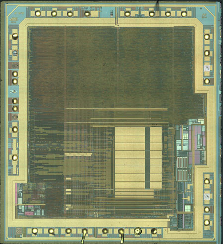
Atmel’s proprietary 0.35 micrometer (μm) wafer fabrication process delivers consistent, repeatable silicon layer construction that simplifies controlled layer removal for lab analysis focused on fuse and lockbit circuitry. The photograph displayed above captures the full ATmega88 die under 200x optical microscope magnification, revealing the major functional block partitions including flash memory arrays, eeprom storage blocks, analog ADC peripherals, and the core CPU logic area. Each segmented block houses unique circuit traces that control memory access permissions defined by the chip’s set of security fuses, which govern whether external debug tools can execute raw memory read-out commands.
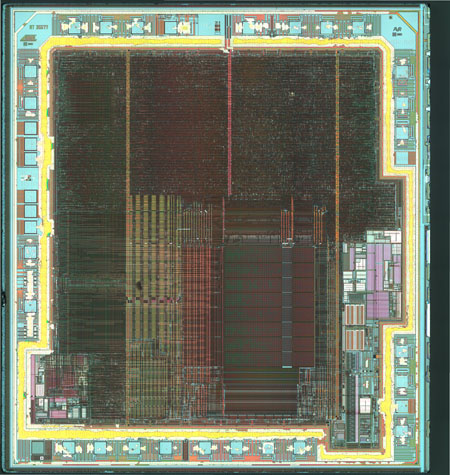
We applied a diluted hydrofluoric acid (HF) bath in precise timed increments to partially dissolve and strip away the outermost top metal layer, labeled M3 on the ATmega88 silicon stack. Partial etching was a deliberate choice rather than full layer removal, as residual metal traces left behind act as visual roadmaps to trace signal paths running down to the lower M2 and M1 metal layers, as well as the underlying polysilicon gate layers. This partial delamination technique is a staple workflow inside any professional fib focused ion beam hack lab focused on microcontroller reverse engineering and internal fuse circuit inspection without permanently destroying critical die landmarks required for mapping unlock logic.
Newcomers to chip decapsulation often make the mistake of fully stripping all upper metal layers in one aggressive acid treatment, which erases critical alignment markers and buried signal busses that link lockbit outputs to flash memory access control gates. Our gradual HF etching method avoids this common pitfall, preserving partial M3 routing traces that we cross-reference across multiple magnification levels to trace how fuse logic blocks block or permit full dump operations on the mcu’s flash array during external programmer communication.
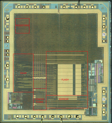
Now that the top M3 metal layer has been partially removed, previously obscured core functional modules on the silicon die become fully distinguishable to our microscope camera and analysis software. The large rectangular SRAM block occupies a prominent section of the chip layout, alongside the dedicated bank of 32 general-purpose CPU working registers that the mcu uses to temporarily hold data during program execution and sensor read-out cycles. These register banks hold intermediate values before they are written to eeprom or flash storage, making them secondary targets for attackers performing real-time signal tapping after decapsulation to reconstruct partial code during early recovery phases of firmware extraction.
Every byte stored inside the SRAM is volatile and lost once the mcu loses power, unlike the non-volatile eeprom and flash arrays that retain data long-term even without a power supply. This key memory distinction impacts how adversaries structure their dump workflows: they must capture SRAM signal traces while the chip remains powered, whereas flash and eeprom data can be extracted offline after successfully bypassing the chip’s lock protection fuses and unlocking memory access permissions.
Earlier in our analysis we described Atmel’s 350nm manufacturing process with the word “awesome”, a sentiment shared by hardware hackers and semiconductor researchers within the maker together club community who regularly perform chip teardowns for educational reverse engineering projects. The orderly layered construction of the ATmega88 die allows controlled partial metal etching that leaves faint residual metal outlines embedded within the silicon dioxide dielectric trenches, which remain visible by adjusting the microscope’s focal depth without fully eliminating the layer’s routing footprint. This subtle visibility feature drastically simplifies tracing long signal busses that run between the configuration fuse bank and the lockbit security logic responsible for restricting unauthorized memory dump and read-out requests.
This manufacturing quirk is far more than a cosmetic detail for silicon security analysts. When attempting to map the electrical path from each fuse’s floating gate to the AND/OR logic gates that enforce memory lock states, residual M3 metal traces act as permanent visual guides that prevent disorientation when switching between 200x, 500x, and even 1000x magnification during decapsulation analysis sessions targeting fuse bypass vulnerabilities.
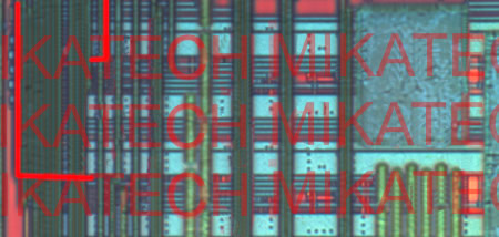
The micrograph shown above, paired with the second fuse-area photo further down, captures the exact same silicon region of the ATmega88 die, with one critical difference between the two shots: the lower image has undergone deeper HF etching to fully clear the M3 metal layer, yet the etched troughs within the silicon dioxide insulating layer still mark the original routing positions where the top metal once rested across the fuse bank polysilicon tracks. These etched indentations create permanent reference lines that we use to cross-verify the signal connections feeding each individual configuration fuse on the mcu.
Atmel integrated over thirty distinct configuration fuses across the ATmega88 silicon layout, each assigned a unique hardware function ranging from system clock speed selection, analog peripheral enable flags, brown-out voltage thresholds, and the critical security lockbit fuses that block external access to flash and eeprom memory. Collectively these fuses form the core hardware security boundary meant to stop third-party tools from initiating a full dump flash operation and completing complete firmware extraction for building duplicate microcontroller-based devices without official licensing.
It is easy to recognize why semiconductor security analysts praise Atmel’s consistent 350nm fabrication workflow after comparing etched layer pairs such as these two fuse close-ups. We successfully removed the opaque upper M3 metal layer that blocked visibility of the underlying fuse polysilicon structures, yet we retain clear positional markers of where the power and signal metal busses originally ran across this sensitive security circuit region. Without these etched trench landmarks, tracing the logic chain from each fuse to the memory lock control gates would require far longer FIB cutting and probing sessions during decapsulation-based reverse engineering work.

These two high-magnification close-up photographs showcase two individual fuse elements pulled from the full set of more than thirty configuration fuses integrated into the ATmega88 microcontroller silicon. One immediate design choice sparks heavy discussion within the hardware hacking community focused on mcu security: Atmel deposited a solid metal shielding plate directly over the floating gate structure of the upper fuse element visible in the frame, a defensive design feature intended to block UV light erasure and physical laser probing attacks detailed on snaileye’s silicon dissection technical guides.
Engineers at Atmel added this metal shield layer in an effort to harden the fuse’s floating gate against simple UV exposure decapsulation tricks that successfully erase lockbit states on older PIC microcontroller families. Despite this countermeasure, advanced FIB and laser cutting equipment found in professional reverse engineering labs can still carve through the thin metal plate to directly contact the floating gate underneath, allowing attackers to manually alter fuse logic levels to unlock the chip’s protected flash and eeprom memory banks for unfiltered read-out and full dump recovery of embedded program code.
We have drawn thin red highlighted signal tracks across each fuse element visible within these paired microscope shots to trace dedicated input and output busses that connect every fuse’s floating gate circuit to the central security logic block housing the ATmega88’s lockbit control gates. Now we pose an open analytical question to readers studying microcontroller hardware security: what functional purpose do these highlighted red polysilicon and metal signal tracks serve within the overall memory access protection scheme built into this AVR mcu?
To expand on this analysis for learners new to silicon reverse engineering: each highlighted track carries a binary logic signal generated by the charge state stored on the fuse’s floating gate. These signals converge into multi-input logic gates that evaluate the combined state of all security fuses and lockbit registers. If the logic gate combination meets the “locked” condition defined by Atmel’s CPU design, all external communication interfaces block every memory read-out and dump request sent from programming tools, safeguarding proprietary code stored inside the flash array from unauthorized firmware extraction used to manufacture unlicensed duplicate hardware products.
Many beginner decapsulation enthusiasts underestimate how interconnected these fuse signal busses truly are. A single cut or short applied to one highlighted track can alter the combined logic output of the lock security block, creating a permanent hardware bypass that ignores the fuse lock state and grants unrestricted access to all flash and eeprom memory contents without modifying every individual fuse element on the mcu die. This single-point vulnerability is the primary target of advanced reverse engineering teams attempting to skip lengthy fuse modification workflows during their dump and code recovery operations.
Another critical educational takeaway from examining these shielded fuse structures is understanding the limitation of passive metal shielding as a security countermeasure. While the M3 metal plate blocks low-cost UV erasure attempts, it cannot withstand precision focused ion beam milling or pulsed laser ablation used in professional decapsulation labs. Once the metal shield is removed, the floating gate becomes fully exposed to electrical probing, letting attackers manipulate fuse charge states to disable lock protection and unlock the microcontroller’s memory arrays for complete flash dump and full firmware recovery.
We also want to clarify the difference between configuration fuses and lockbit fuses for readers new to AVR mcu architecture. General configuration fuses manage peripheral timing, clock sources, and power settings, while dedicated lockbit fuses exist solely to enforce memory access restrictions. Both fuse types feed signal data down the highlighted red tracks we marked in the microscope photos, merging together inside shared logic gates that make the final access permission decision for all external read-out and dump operations targeting flash and eeprom storage.
When performing full reverse engineering on the ATmega88 for duplicate device development, hackers prioritize mapping these highlighted fuse tracks first during decapsulation analysis. By identifying which busses feed directly into the lockbit evaluation logic, they can design minimal laser or FIB cuts that permanently disable memory locking without needing to decode or alter every single configuration fuse scattered across the silicon die, drastically speeding up the entire firmware extraction and code recovery workflow after successfully unlocking the protected memory partitions of the mcu. hardware security research is to improve the overall security
Why choose Mikatech, please click here to find out
Different chip manufacturers have different part numbers, but the inner core of the chip can be make with same technology, it would be quite impossible to list all the part numbers where our technology can apply such as MYSON, STK, FEELING, ANALOG, FUJITSU, NOVATEK, LG/HYNDAI.
Also by the advancing of the technology, everyday we gain more and more experience and develope new methods for reverse engineering for different Intergated Circuit parts. Full list of Integrated Circuit part numbers which is within our scope of capability is always getting bigger, please contact us to find out.
Mikatech Innovative Limited understands the importance of its clients' privacy. At the moment you contact Mikatech, the personal information from you will be put under protection by our management regulations which was developed by our years of practice, Mikatech uses these information to customize its service to you, it will never disclose these information to third party out of any reason.
Every project we did, we will delete all the data, materials, and codes 60days after deliverig the files, it iwll protect us and protect your privacy.
Yes, it is totally legal.
Mikatech deliver its reverse engineering services for educational purposes only, it can be illegal to use above mentioned services in some coutries or regions, please check your local laws.
Mikatech does not take any responsibility in relation to the use of above mentioned services that may be considered illegal.

Years
28
+
|

Countries
110
+
|

Clients
5000
+
|

Projects
60000
+
|