|
Chapter 1
Introduction
 This is the first in a long line of tutorials aimed to provide a beginners guide and tutorial based around the Atmel AVR Atmega32 microncontroller. I will show you, through examples and projects, how to program and provide functions for this microcontroller and what the uses and applications are. This is the first in a long line of tutorials aimed to provide a beginners guide and tutorial based around the Atmel AVR Atmega32 microncontroller. I will show you, through examples and projects, how to program and provide functions for this microcontroller and what the uses and applications are.
With microcontrollers in general, it is good to know that these little chips are found everywhere. You can find them in microwaves ovens, new applicances, automobiles, televisions, etc. These microcontrollers control and sense the surrounding electronics and environment. For example, microcontrollers can provide output to a display, motor, LEDS, etc., sensing the environment, such as tilt using an accellerometer, light, angular velocity using a MEMS (Microelectromechanical System) gyroscope, sound, encoders for movement, temperature, and button or keyboard input.
To give you a basic understanding of the microcontroller, the AVR Atmega32 microcontroller is considered to be a computer on a chip. The microcontroller is able to execute a set of instructions in the form of a program. The program language that I will be using for theseprojects is C++. To giv ethe usersof this website the best opportunity to learn, the C++ programs will be explained is great detail.
The really cool thing about microcontrollers is that you have control over all the pins. For a beginner, this can be a difficult concept to understand, especially having no experience with electronics. Don't fret, I will walk you through each tiny detail. Each pin has a special assignment, or can be used as an input or output feature, with a few exceptions, the power pins.
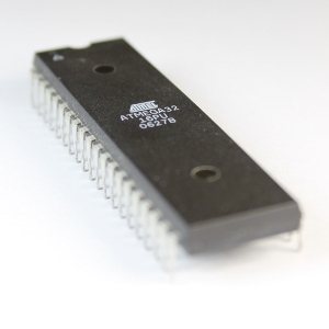
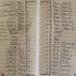 On the left hand side of the chip, looking at it form the top and the little triangle is at the top left, there are 20 pins (this is a 40 pin microcontroller). The first starting from the top left are the PB0-7 pins. That's a total of 8 pins as the index of these pins and most everything in the program starts with an index at 0. This set of pins are called "Port B" and there are 3 other ports labeled from A to D. These ports can be set to receive information and is called INPUT and they can be set to send voltage out in some form called OUTPUT. General power pins to receive the power for the chip called VCC and GND. All but one pin of Port D (PD0-6) is also located on the left side (lower section). PD7 (Pin 7 of Port D) is all alone starting the right hand side of the microcontroller. On the left hand side of the chip, looking at it form the top and the little triangle is at the top left, there are 20 pins (this is a 40 pin microcontroller). The first starting from the top left are the PB0-7 pins. That's a total of 8 pins as the index of these pins and most everything in the program starts with an index at 0. This set of pins are called "Port B" and there are 3 other ports labeled from A to D. These ports can be set to receive information and is called INPUT and they can be set to send voltage out in some form called OUTPUT. General power pins to receive the power for the chip called VCC and GND. All but one pin of Port D (PD0-6) is also located on the left side (lower section). PD7 (Pin 7 of Port D) is all alone starting the right hand side of the microcontroller.
Continuing on the right side, and the ending of Port D, Port C continued from the lower corner up. From there on, may favorite pins continue, the analog to digital pins. These pins have the capability to sense the environment with the help of components that feed these pins an analog voltage. Dopn't worry about not understanding analog or even digita at this point, it will be explained in greter detail later. These analog to digidal converter pins compose Port A.
One example of the use of the analong to digital conversion would be, say, sensing the temperature. You can connect a component that converts temperature to a level of voltage called a thermistor to one of the Port A pins and the microcontroller will convert this voltage to a number from 0 to 255 (an 8-bit number - higher resolution is possible at 10-bits). The program that is written and stored into the microcontroller can use this temperature and respond in a specific way. For example, if you have the thermistor against a boiling pot, the microcontroller can respond and provide an output to another pin that beeps, or flashes a light.
Other features of this and other microcontrollers, other than the actual programming is the programming space (where the program is stored in the chip and how much space you have), memory, or space for data and variables that the program will use, and finally, there is a clock built into the chip that counts. The counting can be in many different speeds depending on the speed of the chip and the divisor that is selected for the speed. This is starting to get complicated, so I will back up. The counting can be in seconds, miliseconds, microseconds, or whatever you determine for the program and application that you select.
As this tutorial series is based on examples microcontroller cloning with scanned electron microscope and focused ion beam service, I will provide a great deal of detail. Of course, the detail for the introduction would be impossible, and if you are very adventureous, you can take a look at the datasheet and manual for this microprocessor, but don't let that huge document sway you from wanting to learn this most incredible technology. Once you lear, there is no limit to the application, from tiny robots, to extremely large scaled architectural wonders that move and give off spectacular lighting effects, sometimes that interact with the environment.
Part 1 - Creating an SPI Interface from the Programmer to the Microcontroller to Make Transferring More Convenient
 So, at this point, you should be familiar with the concept of the microcontroller (MCU). You should also have an appreciation for the general uses of the microcontroller. You have a basic understanding of the pin assignment and the Ports. And, hopefully, you are excited with what a microcontroller can do, like sensing and controlling the environment. Finally, you know that we will get into the programming side of things--given the title of this page, and the fact that we touched on it in the introduction). So, at this point, you should be familiar with the concept of the microcontroller (MCU). You should also have an appreciation for the general uses of the microcontroller. You have a basic understanding of the pin assignment and the Ports. And, hopefully, you are excited with what a microcontroller can do, like sensing and controlling the environment. Finally, you know that we will get into the programming side of things--given the title of this page, and the fact that we touched on it in the introduction).
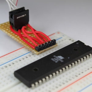
Now we will need to get more in-depth with the programming. However before we can get a program loaded onto the chip, we need a good way to connect the SPI (Serial Peripheral Interface) connector to the chip. We couldn't very well shove the connector into the pins of the microcontroller, now could we? And sticking wires in the end of the connector and into the breadboard is flimsy, unattractive, and possibly harmful to the MCU if a wire carrying voltage is accidentally applied to the wrong pin.
Therefore to maximize our chance of success and standardize each and every connection attempt, we will construct a small board that contains a header (little metal pins that stick up) that the SPI connector can use, and also a header that will correspond to the appropriate pins on the microcontroller snaileye. The latter can simply be a single row of six pins since the makers of the Atmel AVR Atmega32 microcontroller so thoughtfully located these pins together. This will allow us to make our MCU interface board with a very narrow size, which will reduce the area covered on the breadboard (as can be seen in the video). Oh yeah, the video contains a bit of soldering, so you can learn that too!
 Ok, so to reiterate from the last tutorial, there is a programmer that is needed between the computer and the microcontroller. It should be noted that there are several different programmers that can be used, and a suitable model can be had from either Adafruit Industries (USBTinyISP) or Sparkfun (Pocket AVR). Some of these programmers look totally different from others, but all of them basically do the same thing--provide an interface between the computer and the AVR microcontroller. That's it! Note that if you are not using the AVR Atmega32 microcontroller, then you must check the compatibility of the programmer you choose to use. Also note that many of these programmers use the same drivers, an issue which we will get to in the next tutorial. Ok, so to reiterate from the last tutorial, there is a programmer that is needed between the computer and the microcontroller. It should be noted that there are several different programmers that can be used, and a suitable model can be had from either Adafruit Industries (USBTinyISP) or Sparkfun (Pocket AVR). Some of these programmers look totally different from others, but all of them basically do the same thing--provide an interface between the computer and the AVR microcontroller. That's it! Note that if you are not using the AVR Atmega32 microcontroller, then you must check the compatibility of the programmer you choose to use. Also note that many of these programmers use the same drivers, an issue which we will get to in the next tutorial.
The connection between the computer and the MCU is really quite simple, so there should be no reason to be afraid of (or timid with) doing these steps to get a program into the microcontroller. So, let's get to it! Remember that the purpose of making such an interface board, is to insure a proper connection each and every time we need to load our program into the MCU. So if you want to make a board like I've shown in the video, then just get out your soldering iron. Don't be afraid, get it out! Well, you should be careful, as it gets hot. But don't let that get in your way. Just make sure to read all of the manufacturer's instructions on the proper operation of the soldering iron. Also, don't forget to wear goggles; firmware copy and don't breath the solder fumes. Some people use a suction fan to get the fumes away from the workspace.
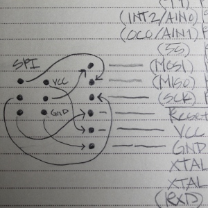
Check out the diagram above. Yes, it's a bit messy, but I drew this while caffeine was flowing through my system! The SPI connector pin-out is to the left. There are arrows from this SPI interface block to the corresponding pins on the AVR Atmega32 microcontroller. There will be no need for fancy components to complicated this process, so don't worry--we are only connecting wires from the SPI device to the pins of the microcontroller.
Let's run through the connections between the SPI device and the MCU:
- Top left SPI pin is connected to the MISO (Master In Slave Out)
- Middle Left SPI pin is connected to the SCK (the clock pin)
- Bottom Left SPI pin is connected to the Reset (Reset just does exactly what is says, and you can be sure we will talk about this pin later!)
- Bottom Right SPI pin is connected to the GND (Ground, or zero volts)
- Middle Right SPI pin is connected to the MOSI (Master Out Slave In)
- Top Right SPI pin is connected to the VCC (+5 Volts, if you want, you can go check voltage requirements in the summary, or the HUGE manual, and trust me, this is not an easy read!).
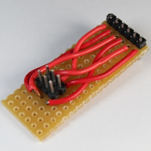 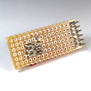
That's it!! All you need to do now is solder the wires between the two sets of headers (remember this term? They're just pins that stick up and insert into a female header). Note that the picture near the top of this page shows the female header plugged into the male header. Once these wires are all connected and soldered-up, it should look something like these pictures. However, if you want to get crazy and do it differently, please go for it!! I encourage creativity.
As can be seen in the pictures, maker together club the connections from the wires to the headers are made using solder bridges. A solder bridge is just solder that "blobs" together to connect two locations. These blobs sort of look like little figure 8's, or infinity symbols. And, it's not too hard to create these bridges. All you need to do is solder the two wire/pin connections like normal, and then add just a little more solder while holding the iron over both of the connections. This will provide enough solder to create the bridge. However, there is the possibility that they won't bridge. Ah, the bane of existence for most solderers...! The bridge is generally not advised in most applications; but in this case, it's simply the easiest way to make the connections between the SPI and MCU pins, and the corresponding wires that connect them. Once you have enough solder applied, and the hot iron is over the two connection, pull the iron straight up along the pin and the bridge should be maintained. Otherwise you may destroy the bridge if the hot iron is allowed to once again make contact with the main body of the bridge. Don't worry--the video shows this very nicely, and you should get the hang of it pretty quickly.
So, wasn't that easy? Now, we will get into the software part of it in the next tutorial. We will find the software on the internet to: First, recognize and drive the USBTinyISP programmer (or, if you choose, the Pocket AVR Programmer); and second, install the development environment. Note that by "driver," I mean to install a driver under the Windows OS, and the "development environment" is simply the application you will use to write the programs that will later be transferred to the chip. If you are using installing this program on another OS, like Linux or the Mac, you will still be able to follow along. Here and there, I may speak of those other wonderful operating systems and how to do things (or find the resources that will help). The programming is the same, but the development environment will probably be slightly different.
Part 2 - Transferring a Program into the Microcontroller
By now, you should have constructed the SPI interface. If not, you can either review the previous tutorial, or live with the flimsy wires. If you have read the first sentence more than two times after constructing the device I presented in the last tutorial, don't worry...the thing you made is the SPI 聚焦离子束FIB服务 interface! It's simply the 6-pin cable, wired to a straight set of 6 pins that match the proper pin arrangement on the microcontroller.
At this point though, we need to make sure the computer will recognize the programmer. This is the USBTinyISP device from sparkfun or adafruit industries, that connects the computer to the microcontroller. Like everything in this universe that plugs into a computer loaded with the Windows operating system, there is a need for drivers--and this programmer is no exception. However my video will provide you with instructions for the complete installation of these drivers, so there is no more guessing!
Since I am installing the driver on my computer running the Windows 7 64-bit operating system, the installation is somewhat different than the procedure for the 32-bit operating system. No need to worry though--if you can click and drag files from one folder to another, you will not have a problem. Apparently, the drivers from sparkfun.com do not contain the latest version of the 64-bit drivers. This is completely explained in the video however, so you should have no problem installing the driver if you are running a 64-bit system.
Here are the general steps to get the drivers on the system, and the programmer recognized by either a 32-bit or 64-bit Windows operating system.
- Go to sparkfun.com and navigate to the Pocket AVR Programmer page (left pane under "Programmers - AVR") . The link is supplied so you don't need to pay attention to my overly verbose description.
- Enjoy the beautiful red, black and white color scheme.
- Scroll down and find the Windows Driver link under Documents. Or, ahem, just click the link.
- Now you have the pocketprog-driver.zip file on your computer somewhere. Let's hope you know where it downloaded! If you do, whew...! Unzip the file into another folder for which you know the location.
- Before you fiddle with the contents or try to install it for some reason, a couple of files need to be revised for the 64-bit version of Windows 7 or Vista. However, if you are using a 32-bit version of Windows, go ahead and start the installation. You can simply disregard the following explanation for the 64-bit procedure.
- Now, go to the libusb sourceforge page and click on the latest release.
- You will see a few or more files listed. You want the bin file (i.e. libusb-win32-bin-#.#.#.#.zip).
- Now you have another .zip file to find on your computer. Go ahead and unzip it into a known location.
- Go into that folder and navigate to the bin folder, then into the amd64 folder. There will be two files there ghcalled libusb0.dll and libusb0.sys. Rename these files to libusb0_x64.dll and libusb0_x64.sys.
- Copy these files into the pocketprog-driver folder, overwriting the existing version of these files.
- For installation of the newly downloaded drivers, I will show a rather non-traditional method which I like very much. This is the "add legacy hardware" mode. Yes, there is such an animal in Windows!
- Click on the Start menu.
- Right-click on "Computer"
- You will see a menu... select the "Manage" option. It will probably have a yellow and blue shield next to it.
- Click on "Device Manager". Yes, I know you know of a different way to get to the device manager. Well, now you know another way.
- Right-click on the top of the list (the computer name, typically ends with a "-PC." Mine is patrick-PC). You guessed it, my name is Patrick.
- On the menu, select "Add Legacy Hardware." If you are wondering, "Legacy" means hardware that is still in use and has been for a while; or hardware that Windows does not have on their all-powerful hardware list. Well, that's my definition for it anyway...
- Press "Next" when the wizard is introduced.
- On the next screen, select "Install the hardware that I manually select from a list (Advanced)," so the radio button is changed to that selection. A radio button is a windows control that looks like a circle with a small blue spherical dot in the center.
- Click Next
- The "Show All Devices" option should be highlighted. Make sure of this and click next.
- Click on the "Have Disk" button.
- Using the "Browse" button, navigate to where the pocketprog-driver folder is located. If you selected the correct folder, you will see the pocketprog.inf file located in that folder. Double-click this file and the driver should start to install.
- Review this procedure again, or watch the video a second time if the installation doesn't seem to go as planned.
Part 3 - Installing the Programming Environment and Getting to Know a Little Bit About it
To be able to make the microcontroller do something useful, we must write instructions for it to follow. While we can write these instructions with a simple text editor, many people find it much easier to use a dedicated "programming environment" to write their programs. The video in this tutorial takes you through each step needed to install one such programming environment (WinAVR) on the computer. I call it a programming environment because the program you will install has many features. This particular programming environment allows you to create and edit programs in various languages (we will focus on C), and then compile the program into an executable format that the microcontroller will understand. Finally, WinAVR will help us transfer this file into the microcontroller. WinAVR will also help us to do many other things, like debugging our programs and giving warnings when there are compilation and syntax errors. We will get into the particulars of these in later tutorials.
The installation process for WinAVR is very quick and concise. Here are the detailed steps:
- Download the latest files from the WinAVR sourceforge files location. The official website has some information relating to the program, if you are inclined to explore it further.
- Click on the latest release.
- You will need to answer the security question asking whether you want to save the download or not, since you will be downloading an executable file.
- Once it is downloaded, execute the file by clicking on it. The installation process will start.
- The installation process will have the usual Windows install wizard information, and some questions offered to help you tailor the process. Most of these can simply be left as their default value, but select as you see appropriate.
Well, that's pretty much it for the installation. Not much different than the installation for most Windows programs. But you will probably notice the many options in the start menu folder for the WinAVR programming environment. Don't fear, you will typically use only one of these programs called the "Programmers Notepad." Clicking on this icon will start the user interface for the application that allows us to write our programs (creation and editing). The program also contains menu commands that will help us compile the code and then transfer it into the microcontroller.
Ok, so you may still be rusty on the compiling process. Recall that it's just the process where the computer converts the human-readable program you wrote into a set of instructions that the microcontroller can understand. The programmers notepad will take care of all of this for us behind the scenes, so we don't have to concern ourselves with all the details. You can, however, learn more about the process if you wish.
In the next video, we will test our configuration and installed components. The programmer will be tested so we can confirm that it is recognized by Windows, and it is fully able to communicate with the microcontroller device. We will then write a short "Do nothing" program to make sure there are no errors when we transfer the program onto the microcontroller.
Chapter 1 | Chapter 2 | Chapter 3 | Chapter 4 | Chapter 5 | Chapter 6 | Chapter 7 | Chapter 8 | Chapter 9
|