|
Chapter 2
Part 4 - Testing the USBTiny Programmer and Building the First Circuit for Programming
So far, you should have all the software installed and constructed the interface that will provide a convenient connection from the programmer to the microcontroller (MCU). For the next step, you will need a breadboard (the ones with numbers are very helpful), an LED, and a resistor of a size appropriate for the chosen LED. You will learn in this section how to test the programmer to determine if the software and drivers were installed correctly. You will also learn a little bit about LED lights, Ohm's law, and the resistance value required for the chosen LED.
To check to see if the drivers and the development software installed correctly, we will test the programmer with a program called avrdude. Avrdude is a program that is installed with the latest WinAVR installation, and is responsible for the actual transfer of the file going into the microcontroller . This is the .hex file, which is basically the binary code that the microcontroller can understand and execute. If the test is not successful, the programmer will not be able to transfer the file--therefore this step is crucial to the whole process. To test the programmer, follow these steps:
- Go to a DOS prompt by clicking the start menu and typing cmd.exe in the search box. By the way, if you didn't know, DOS stands for Disk Operating System. This was a prompt created so computer users would be able to organize their files on floppy disks, thus making it easy to execute (run) programs from the DOS Prompt. Prompt means snaileye the place where the cursor is located and you can start typing. The prompt is labeled with the drive letter along with the folder name separated with backslashes "\". (We called these directories in the past.)
- To execute the avrdude program that was installed with WinAVR, simply type avrdude -c usbtiny -p m32 at the DOS prompt, and the DOS shell output will report the success of the connection. The "-c" is a flag that is followed by the parameter used to specify the programmer (usbtiny), and the parameter following the "-p" flag is used to specify the microcontroller ("m32" for the Atmega32). If you are using a different microcontroller crack, you will need to use the appropriate specification, as shown in the video for this tutorial.
- To exit out of the DOS window, you can type "exit" at the DOS prompt and the DOS window will disappear... just like my ephemeral kids in Disneyland!
So, you probably wonder, why can't we program yet! Well, we still need to create a circuit that the program will control. It would be pointless to simply load a program into a microcontroller and run it without any devices connected to it. We wouldn't have much to look at! In fact you will soon see that many electronic components can be controlled by microcontrollers, however one of the easiest devices to control is an LED.
"LED" stands for Light Emitting Diode, and this component generally has two leads. Leads are the metal legs (wires) hanging off of the actual LED itself. These leads are the polar connections that allow current to flow into the LED from one lead (called the anode) and then out of the LED from the other lead (called the cathode). One very important caution about powering and using LEDs: The current running through the LED must be limited so it does not burn out. LEDs have both a current rating, and a voltage rating. The current rating is the maximum current limit that the LED can handle--any higher current and the LED life will be shortened; but less current will result in a dimmer LED that does not emit light as brightly. So, we are faced with having to compute the optimum value for the resistor we will choose. Note that if you don't want to do this calculation for some reason, it is generally safe to use a 1k--but the light will be pretty dim.
So to calculate the resistance needed, we will use Ohm's law which states that resistance (in Ohms) is found by dividing the voltage by the current. The formula is:
Resistance = volts/current
This is typically written as R = V / I. But, how do we find the voltage and current values for the LEDTypically, LEDs are rated at either 2 or 4 volts, and have either a 10 milliamp (mA) or 20mA current rating. My green LED has a 2 volt rating. In the website linked in the previous sentence, white and blue LEDs have a voltage rating of 4 volts. I used the 10mA rating since it is safer to use this value as it results in the smallest denominator in the Ohm's law formula, and thus represents the largest resistance value for a given voltage. Therefore it can be considered the "worst case scenario," in terms of choosing a resistor to insert into the circuit. Another aspect we will need to consider is the difference between the supply voltage (the voltage we are feeding into the system), and the rated voltage of the LED. So therefore the new formula becomes
R = (Supply Voltage - LED Voltage) / I
Therefore in the case of our green LED, R = (5v - 2v) / .01A = 300 ohms. Oh yeah, you need to convert the current to amps. Therefore we need to divide the 10mA number by 1000, as there are 1000 milliamps in one ampere. So now, what is this formula telling us? It's telling us that the resistance is equal to the remaining voltage after the LED is considered (i.e.; the voltage drop across the LED), divided by the desired current through the LED.
What is that you say? We got a value of 300 out of that formula, but when I went to the store I couldn't find that number! I hate to tell this, but the money spent on gas for that trip could have bought you 40 of the correct resistors! 300 Ohms is a resistance that is probably not available, but don't lose hope--you can always use a resistor of the next highest value. I have found this to be 330 Ohms in the mix of resistors I've collected from various thrown away appliances and electronics.
Now we'll create the circuit, which is pretty simple in this tutorial. The hard part is behind us (the stuff above), so you can wipe your brow now! Let's use Pin 0 of PORT "B" on the MCU in this circuit, and that just so happens to correspond to the number 1 pin on the Atmega32 maker club microcontroller I am using. So now we are going to programmatically turn on that pin to light up the LED.
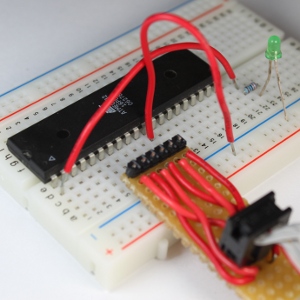
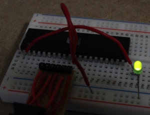
The steps to create the circuit go like this: Connect the resistor to the pin number 1 (note that saying "PORTB0" is one way of referring to pin B0 of PORT B, but you'll learn other ways as well). Now connect the other end of the resistor to the positive side of the LED (i.e.; the anode side, or the lead that is the longest, or the lead opposite to the flat of the LED). Then we will connect the cathode side to the ground (GND) pin. The programmer will be connected too of course; which will allow the program to get transferred into the chip, and also provide power to the microcontroller. Finally, we can now apply the circuit to the breadboard. The videos demonstrate all the steps needed in this process. From the accompanying image, you can see that this is a very simple circuit.
Now apply the circuit to the breadboard. The videos demonstrate this with every step needed. From the image, you can see that this is a very simple circuit.
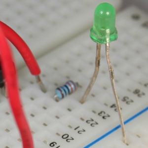
Check out the close-up of the resistor and the LED. Can you see how the wire is connected to the resistor and how the resistor is connected to the LED? After this circuit is completed on the breadboard, we can start to program and make the LED light up. Excited? I am!
Part 5 - Writing the First Program to Turn On an LED and Transferring the Program into the Microcontroller
I know that you are ready to write the first program. You have been through a lot so far! While we are on the subject, let's recap the events. You went out and purchased the AVR Atmel Microcontroller of your choice. I chose the ATMega32 for my uses. You were introduced to the concept of microcontrollers how they work; and were also introduced to the programmer, the device that helps transfer the program into the microcontroller. You built a convenient interface that is used to connect the SPI pins to the correct pins of the microcontroller. You verified that the programmer (USBTinyISP) drivers were installed correctly for the 32-bit and 64-bit versions of Windows (XP, 7 and Vista). You also installed the programming environment installed the "Programming Environment" called WinAVR microcontroller Cross Section Failure Analysis with FIB focused ion beam serivice so that you can have an environment in which to write your program, and then transfer it into the microcontroller. And to make sure that everything functions correctly, you used avrdude to tested the programmer while plugged into the computer and the microcontroller. Recall that this program is the program transfer utility to move our compiled program into the memory on the microcontroller. Finally, you built the first circuit so that we could have something to write a program for. Whew... that was a lot! But since you jumped through all of those hurdles, the hard work is over and it's smooth sailing from here on. Hopefully you were able to get through the previous steps without any problems--so now let's get on with our first program.
For the sake of simplification, let's categorize the function of the microcontroller into three categories: Control, sensing and communication. We'll leave the details of how to develop each of these functions, and delve into these details as we write the various programs. Note that there are many ways to program these functions. For the first program, we'll make the microcontroller "control" something. And as you know from the previous post, we'll be using an LED for this purpose. Basically, we will turn the LED on. Yes I know... boring, right? Well I need to start somewhere! As I take you through the experience of programming, I will add more complexity a little at a time so you are easily able to wrap your head around these important concepts.
 So at this point you're probably asking...how do we make a program to control an LED? Well, it's really easy: We will simply tell Pin0 on PORTB to output 5 volts. Remember that this is the pin to which the positive lead (anode) is connected. The first key in this scenario is "output, " and the next is "5 volts." There is a way we can tell a particular pin to be set to be an output from the MCU. Once a pin has been set to provide output, you will then be able to control that pin and make it either high (5 volts) or make it low (zero voltage). And since there are only two states for this pin in the output mode (5v or 0v), and only two states for the mode itself (input or output), you only need to set the value to either logical 1 or a 0. Note that this must be accomplished for each pin we wish to use in our circuit. But before we get to plugging in a 1 or 0, let's talk about input versus output. When a pin is in input mode, it is listening for a voltage. When the pin is in output mode, the it can be charged at 5v, or not charged at 0v. That's it! So at this point you're probably asking...how do we make a program to control an LED? Well, it's really easy: We will simply tell Pin0 on PORTB to output 5 volts. Remember that this is the pin to which the positive lead (anode) is connected. The first key in this scenario is "output, " and the next is "5 volts." There is a way we can tell a particular pin to be set to be an output from the MCU. Once a pin has been set to provide output, you will then be able to control that pin and make it either high (5 volts) or make it low (zero voltage). And since there are only two states for this pin in the output mode (5v or 0v), and only two states for the mode itself (input or output), you only need to set the value to either logical 1 or a 0. Note that this must be accomplished for each pin we wish to use in our circuit. But before we get to plugging in a 1 or 0, let's talk about input versus output. When a pin is in input mode, it is listening for a voltage. When the pin is in output mode, the it can be charged at 5v, or not charged at 0v. That's it!
There are many ways to do this. This is not to confuse you, but rather to make things simpler. I will be introducing you to one of the many ways to accomplish this task, and later I will explain some other methods while writing other programs. Note however that while this first method is great for introducing the concept, it's probably not as good in practice. Therefore you will see other methods in future programs that will leave contextual pins (those pins on either side of the pin of interest) unaffected, as they may very well have been previously set in the program. But since we're writing a simple program, we won't worry about this complexity at this time.
To pick the output mode for a pin, you will use the Data Direction Register (DDR). Oh man! What is a register?!? Don't let this worry you. A register is simply a memory location that makes the microcontroller react in some way. We use a register to set a state for the microcontroller, or make the microcontroller do something. It's like reflexes, or tickles. When a person tickles another person, it invokes laughter. We can make the MCU do something by setting a specific value in a register. That's all you need to know at the moment.
So when you use the DDR register, you are able to set the pin to either output data, or accept data input. But we said input or output, now you're saying data also. The term "data" used here simply just adds another dimension to this idea in the form of "time." If you make a pin 5 volts, then zero volts, and then 5 volts again...you are actually sending 1s and 0s. To the pin, this is nothing more than a high (5 volts) state, and then a low (zero volts) state: The MCU sees this high/low logic. And you can also receive data in the same way.
There are several ways to set pin0 for port B to output. One way to do this is to write:
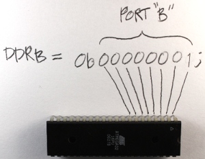
DDRB = 0b00000001;
Let me explain. "DDRB" refers to the Data Direction Register for port B; "0b" is to tell the compiler that what follows is the binary expression of a number; and the "1" on the end denotes the pin 0 position (the first pin in port B). Recall that there are 8 pins for port B; pins 0 though 7. There are also 8 digits in our line of code. So each digit represents a pin on the port, and we can use the individual digits to specifically refer to any one of the pins in port B. So the '1' at the end of our code 扫描电子显微镜SEM拍照提图 statement refers to the first pin in port B, which in this case is pin 0. (Recall that C and C++ are zero-based languages, so the first index of a data structure refers to is the zero'th element; the second index refers to the first element, etc.) We really don't need to get any more complex at this point, as this will be covered in much more detail in future tutorials. However if you would like to know more about the binary system, check here.
 Now we need to apply 5v to the pin. This works just like the DDR code statement we used above. We will use a binary number to put 5v on that pin (pin 0) using this statement: Now we need to apply 5v to the pin. This works just like the DDR code statement we used above. We will use a binary number to put 5v on that pin (pin 0) using this statement:
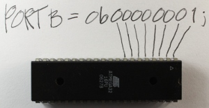
PORTB = 0b00000001;
The only difference between this and the previous statement is that we are now using the PORT register. This register knows the pins of that specific port, and gives us access to specify the actual data value (logical 0 or 1) for these pins.
Now we need to talk a bit about the overall structure of our program. All programs need a specified place to start the execution. It's like giving someone a set of instructions on how to make a cake without telling them which step to start on. The "main" function is the place where all C/C++ programs start execution. So we will create a main function.
int main(void)
{
}
In order for the program to understand the DDR and PORT register information and how these work within the microcontroller, an include statement must be added that contains all of the information about the AVR microcontrollers. This include statement will probably be in all of your programs.
#include <avr/io.h>
int main(void)
{
}
When the compilation process starts, the pre-processor portion of the compiler looks in the "avr" directory for the "io.h" file. The ".h" extension here indicates that this is a header file, and (as its name implies) the code within that file will be inserted at the beginning (head) of the source file you are creating. Now we can insert the DDR and PORT statements into our code, since the inclusion of the io.h header file has informed the compiler about them.
#include <avr/io.h>
int main(void)
{
DDRB = 0b00000001; //Data Direction Register setting pin0 to output and the remaining pins as input
PORTB = 0b00000001; //Set pin0 to 5 volts
} Now the direction of the pin0 is set to output, with a value set at 5v. But we are still not finished. We need to keep the microcontroller running indefinitely, so we need a routine to do this. This is called an endless (or infinite) loop. The infinite loop makes sure that the microcontroller does not stop performing its operations. I will explain this in more detail when we have stuff to do within this loop. There are several types of loops we can use for this purpose, but for this demonstration I will use the while loop. It means the same in English as it does in code: For instance, "while" I have my hand up, you should keep clapping.
#include <avr/io.h>
int main(void)
{
DDRB = 0b00000001; //Data Direction Register setting pin0 to output and the remaining pins as input
PORTB = 0b00000001; //Set pin0 to 5 volts
while(1)
{
//Code would be in here if it needed to execute over and over and over ... endlessly
}
} Note that we use a '1' as the argument to the while loop, because anything other than '0' is a logical true. Therefore the while loop condition will never be anything other than logically true, and the program will continue to execute indefinitely (i.e.; I keep my hand raised).
 So, here is the fruit of our labor. It was a long ride so far, but I promise, everything from here on will be gratifying and far less time consuming. In the next video and instruction, we will make the LED blink. We will investigate how to create a delay so the LED does not blink so fast that it looks like it's not blinking. So, here is the fruit of our labor. It was a long ride so far, but I promise, everything from here on will be gratifying and far less time consuming. In the next video and instruction, we will make the LED blink. We will investigate how to create a delay so the LED does not blink so fast that it looks like it's not blinking.
Chapter 1 | Chapter 2 | Chapter 3 | Chapter 4 | Chapter 5 | Chapter 6 | Chapter 7 | Chapter 8 | Chapter 9
|