If MikaTech was a bad company, you could find tons of bad reputations about its service on the internet over the 28 years history
So, the answer is YES! We are good people.Why choose Mikatech, please click here to find out
 MikaTech Lab - Slide
 MikaTech Lab Started
 MCU Decap Room
About MikaTech
Time went fast, from the day we did our first 8051 MCU reverse engineering project in 1998, to the day we set up our million dollar reverse engineering lab in 2012, 14 years went by. Now we start our new business of embedded visual system development, hope we can serve another 10 years.
 Peter Lee
Co-Founder & CEO
Peter Lee
Co-Founder & CEO
Chapter 3
After finishing the simple static LED lighting program for your ATmega32 microcontroller (also shortened as mcu), you have laid the most basic foundation of embedded C programming. That original code could only keep the light steady without any dynamic change, which is too plain for practical testing. Now we will upgrade the program to generate a blinking LED effect, and this revision also introduces core bitwise logic operations that form the backbone of all advanced mcu firmware design. Mastering these bitwise operators is not only critical for normal peripheral control, but also essential if you later need to analyze raw dump data or conduct legitimate code recovery after authorized read-out of flash and eeprom memory. Attackers who specialize in reverse engineering duplicate hardware rely heavily on bitwise parsing when they dump flash memory after bypassing the chip’s lock and unlock security layers, so understanding these operations also helps you design firmware that resists decapsulation-based hacking. The updated blinking program has a concise structure, yet it hides multiple critical hardware control concepts that every embedded developer must memorize and practice repeatedly.
You can review the complete revised source code sample right below, which integrates delay functions and bitwise toggle logic:
Many new learners feel confused by special symbols such as |=, ^= and << in this code snippet, and these bitwise operators may look unintelligible at first glance. This section will break down every operator with plain explanations and binary examples. You do not need to fully grasp complex logic at the first reading; you only need to remember what each combined statement achieves for mcu pin configuration. Before diving into code analysis, we first clarify the four core bitwise logical operators: AND, OR, NOT and XOR, all of which manipulate individual binary bits (0 and 1) that make up every byte stored in microcontroller flash, eeprom or temporary RAM. When attackers complete a full dump after they unlock a chip by tampering with fuses or lockbit registers, all captured binary dump files rely on these same bitwise rules for reverse engineering and code recovery work.
The AND operator compares two corresponding bits from two binary values simultaneously. It outputs a logic 1 only when both input bits equal 1; all other combinations return a logic 0 value. This rule applies no matter if you are processing runtime RAM data or static firmware code extracted via dump flash read-out after decapsulation hacking. For instance, 1 AND 1 = 1, while 1 AND 0, 0 AND 1 and 0 AND 0 all generate a 0 result. The ampersand symbol & stands for the AND operation in standard C language for AVR mcu development.
Example binary AND calculation demonstration:
The OR operator works even more intuitively for embedded programming workflows. Its core rule states that if either of the two matching bits is 1, the output bit will be set to 1; only two simultaneous 0 bits produce a 0 result. The vertical bar | represents OR in AVR C code, and this operator is widely used to set single GPIO pins without altering other port bits, which prevents accidental corruption of critical signal lines that store fuse or lock status data inside mcu eeprom.
We use the same two 8-bit binary numbers for the OR example below:
As shown in the calculation result, every position that carries a 1 in either original binary number becomes a 1 in the output value. This unique trait makes OR the primary operator for activating single microcontroller pins while preserving the original logic level of all remaining port pins. The NOT operator performs a simple bit flip: every 0 bit turns into 1, and every 1 bit flips to 0 across the entire binary sequence. Unlike AND and OR, NOT only takes one binary input value, and it is frequently paired with AND to clear specific pin bits during mcu peripheral configuration, which also helps developers erase sensitive lock information from eeprom before third-party dump analysis.
The XOR operator shares partial similarities with OR but has one vital difference: XOR returns 1 only when the two compared bits are different values (one 0, one 1). If both bits are identical (both 0 or both 1), XOR outputs 0. The caret symbol ^ denotes XOR in embedded C, and this operator powers the LED toggle logic in our blinking program. Malicious actors use mass XOR masking during reverse engineering to obfuscate recovered code after they dump flash data and create unlicensed duplicate mcu hardware.
Now we analyze the newly added header file in the sample program: #include <util/delay.h>. You already understand the function of avr/io.h which defines all microcontroller register addresses including DDRB, PORTB and memory locations storing lockbit and fuse configuration data. The delay header file supplies built-in millisecond and microsecond delay functions such as _delay_ms(), which suspend mcu program execution for a specified time period. Without delay logic, the LED toggling speed would far exceed human visual perception, and the blinking effect becomes invisible to observers. When conducting legitimate firmware extraction testing, engineers also utilize these delay functions to analyze how timing loops are stored inside dump flash binary files.
We first compare the old pin configuration code with the improved bitwise version to highlight the huge advantage of bitwise operations. The original statement DDRB = 0b00000001 overwrites all eight bits of the Data Direction Register in one operation. If your later mcu program assigns other pins as input or output signals (such as buttons, sensors or communication buses), this crude assignment will erase all pre-set pin modes and trigger functional failures, or even expose critical lock logic stored on adjacent port traces to potential read-out probing.
To modify only Pin0 without changing other port bits, we combine the OR operator with a dedicated binary mask. A mask is a custom binary sequence that isolates target bits for modification, and it acts as a simple hardware-level filter when adjusting mcu register values. The full statement DDRB = DDRB | 0b00000001 reads the original DDRB register value first, then performs a bitwise OR operation with the mask to only set the least significant bit to 1, leaving all seven upper bits completely unchanged.
C language supports combined assignment operators to shorten this repeated expression into a cleaner format DDRB |= 0b00000001, which carries identical execution logic and reduces redundant code volume in large mcu projects with dozens of peripheral control routines.
We can further optimize the mask writing method by using the left shift operator << and pre-defined pin macros like PINB0 from avr/io.h. The expression 1 << PINB0 generates the exact same binary mask 0b00000001 we used earlier. The digit 1 represents the logic high bit we want to place in the target position, while << shifts this single 1 bit leftward by the number of positions specified by PINB0 (which equals 0 for Port B Pin0). If we replaced PINB0 with PINB4, the expression 1 << PINB4 would shift the 1 bit four positions left to form the mask 0b00010, a convenient syntax when configuring multi-pin sensor arrays on the same microcontroller port. Attackers analyzing dump data from decapsulated mcu chips spend lots of time decoding shift operations to reconstruct original pin assignment logic during code recovery for duplicate device production.
Next we break down the infinite while loop that contains the core LED toggle logic. The static lighting program only configured pin modes once before entering the empty loop, so the LED held a fixed voltage level permanently. To create visible blinking, we must repeatedly switch Pin0 between high and low voltage states inside the loop body, and insert delay intervals between each voltage flip. Without _delay_ms(), the mcu executes the PORTB toggle operation millions of times per second, and human eyes cannot distinguish individual light on/off cycles. Every delay function consumes mcu CPU cycles to pause program flow, which also creates a small timing vulnerability that glitching attackers can exploit to temporarily unlock lock barriers during unauthorized read-out of eeprom and flash dump data.
We can split the toggle logic into two separate steps using OR and AND-NOT operations to clearly demonstrate pin high/low switching. The first line sets Pin0 to logic 1 to light the LED, followed by a 100-millisecond delay. The second line clears Pin0 to logic 0 to turn off the LED with another delay inserted afterward. The expression ~(1 << PINB0) generates an inverted mask where only the Pin0 bit equals 0, and combining it with the AND operator clears the target bit while preserving all other port signal values. This two-stage toggle format is easier for absolute beginners to read, though it adds two redundant delay lines compared to the XOR shorthand.
Since the on and off delay durations match in this blinking demo, we can simplify four lines of logic into two concise statements using the XOR operator. PORTB ^= 1 << PINB0 flips the logic state of Pin0 every time the line runs: if the pin was high, it switches low, and vice versa. This single line replaces two separate pin modification commands and reduces the total lines of firmware code stored inside mcu flash memory, lowering the file size of any dump captured during read-out attempts.
This compact bitwise blinking routine forms the foundation of countless embedded indicator light projects, and all its core logic is easy to replicate for other mcu peripheral control tasks. Mastery of shift, OR, AND and XOR operators eliminates the risk of accidentally overwriting unused port bits that store critical fuse status and lockbit security values inside your microcontroller’s eeprom storage, which prevents hackers from extracting full hardware protection rules via dump and reverse engineering workflows.
After mastering LED output control and bitwise register manipulation on your ATmega32 microcontroller, you are ready to integrate manual human input hardware into your breadboard circuit. Buttons and mechanical switches act as the most straightforward interactive input devices for all mcu-based embedded systems, and learning button reading logic lets you build responsive interactive projects ranging from simple light controllers to complex industrial trigger equipment. A standard desktop keyboard is essentially a massive matrix of individual button switches that send ASCII character signals to the host microprocessor or mcu core, and every key press relies on identical input reading logic we will implement in this tutorial. When designing commercial mcu products with button interfaces, developers must add hardware anti-tampering shielding to exposed switch traces; otherwise, adversaries can tap these signal lines during decapsulation and read-out operations to gather clues for unlocking fuses and lockbit memory partitions.
At this stage of the tutorial series, you have completed full WinAVR toolchain installation on your Windows system, mastered avrdude programmer testing procedures, built a basic LED circuit, and written functional firmware to produce stable blinking effects on the ATmega32 microcontroller. All prior learning steps build the prerequisite knowledge required to handle digital input signals from physical button hardware, and every new coding skill we cover here will transfer seamlessly to sensor reading, serial communication and secure lock state monitoring on advanced mcu designs.
Microcontroller input hardware falls into two broad classifications: voluntary human-operated devices including buttons, touch panels and keyboards, and automatic environmental sensors such as accelerometers, temperature probes and infrared receivers that collect data without manual user interaction. Buttons represent the most accessible entry point to digital input programming, yet mechanical switch hardware carries an inherent flaw known as signal bouncing that distorts voltage levels transmitted to mcu GPIO pins. Unfiltered bounce signals create false input triggers that corrupt program judgment logic, and this hardware defect must be resolved via either external capacitor circuits or internal software delay subroutines. Attackers who conduct dump flash extraction on unprotected button firmware often exploit unprocessed bounce logic to inject fake input signals and bypass runtime lock verification subroutines stored in the microcontroller’s eeprom.
Mechanical button bounce occurs because internal metal contacts inside the switch vibrate rapidly for several milliseconds after being pressed or released, creating fluctuating voltage signals that alternate between 0V and 5V instead of delivering a clean stable logic level. If the mcu reads the pin voltage mid-bounce, it misinterprets one single button press as dozens of separate input events, breaking all interactive control functions. Every household appliance and automotive control panel solves this bounce issue with standardized filtering designs to avoid erratic behavior that could compromise safety lock logic built into the main mcu firmware.
Two mainstream debounce solutions exist for microcontroller circuits: hardware filtering with a parallel capacitor, and software filtering with timed delay checks. The hardware method connects a small capacitor across the two button terminals to smooth fluctuating bounce voltages into a steady signal that the mcu can reliably sample. This physical component solution reduces CPU workload by offloading signal conditioning work to passive electronics, avoiding extra code bloat in flash memory that would expand the size of any dump file captured during unauthorized read-out operations. Software debounce adds delay statements after every detected button edge to wait out vibration periods, but extra delay logic increases firmware complexity and introduces new timing attack surfaces that malicious actors can abuse to unlock security fuses.
The appropriate capacitor value for hardware debounce depends heavily on the bounce severity of your specific mechanical switch. Low-capacitance components around 1nF deliver minimal voltage smoothing and barely suppress bounce noise, while medium-value 220nF capacitors fully stabilize fluctuating signals for most low-cost plastic buttons used in hobby mcu prototypes. Even the 220nF variant generates rapid voltage transitions fast enough to avoid perceptible input lag for human operation, making it the universal recommended choice for beginner embedded circuit construction.
Your breadboard layout can be optimized for clearer wiring when adding multiple components such as buttons, LEDs and associated resistors. Splitting a single breadboard into two connected segments creates extra layout space and keeps jumper wires short to reduce electrical interference that distorts analog and digital signals linked to the mcu’s eeprom read circuits. Align the ATmega32 microcontroller’s pin numbers with the printed row markers on the breadboard to eliminate repeated pin-counting during wiring work, and link all shared 5V VCC and GND rails between both board segments to supply power anywhere on the prototype without long power jumpers. Neat compact wiring also limits the number of exposed PCB traces that intruders can probe to capture unencrypted signal data during decapsulation and dump workflows targeting your microcontroller’s internal memory.
The firmware modifications required to integrate a button into our existing LED blink program are minimal and straightforward. We only need two extra register initialization lines before the main infinite loop to configure Port B Pin1 as a digital input with an internal pull-up resistor enabled. The pull-up resistor holds the pin at steady 5V logic high voltage when the button remains unpressed; pressing the switch connects the pin directly to GND to pull the signal down to 0V, creating a clear distinguishable input trigger for the mcu to detect in code.
The above bitwise AND-NOT statement clears the Pin1 bit inside the DDRB register, setting this port line to input mode and isolating it from output driver circuits that could interfere with button voltage sampling. Next we enable the built-in pull-up resistor by setting the Pin1 bit high within the PORT register:
With pin initialization complete, we add a conditional if-else branch inside the main while loop to adjust LED blink speed based on the button’s electrical state. The built-in bit_is_clear() helper macro checks whether the target pin’s logic level reads as 0 (button pressed) by scanning the PIN register’s corresponding bit position. This conditional structure lets us assign distinct delay values for pressed and unpressed button states to create visible interactive differences in the LED blink rate, and the same conditional syntax can be expanded to validate fuse and lockbit statuses in secure production mcu firmware to block unauthorized dump and duplicate generation.
Inside the if branch (button pressed state), we assign a short 10-millisecond delay to make the LED blink rapidly; the else branch uses the original 100-millisecond delay for slow blinking when the button remains untouched. This simple interactive logic demonstrates how mcu firmware can dynamically adjust runtime behavior based on external hardware input signals captured via GPIO pins, and the code structure is fully expandable to build complex authentication routines that check unique eeprom serial numbers before permitting device unlock to prevent reverse engineering and firmware extraction.
Full revised source code integrating button input logic is displayed below:
This complete interactive program requires only a handful of new code lines beyond our original blinking firmware, proving how flexible bitwise pin configuration and conditional branching make embedded mcu development for beginners. Every core technique demonstrated here transfers to larger commercial projects that implement physical access buttons to trigger secure memory lock operations that block dump flash read-out and invasive decapsulation attempts on production microcontroller hardware.
Proper button debounce handling is an indispensable programming and circuit design skill for all mcu developers, as unfiltered switch bounce creates chaotic, unreliable input responses that break every interactive embedded project. End users expect one single button press to trigger exactly one corresponding action such as LED state toggling, LCD menu navigation or motor activation. If bounce noise remains unprocessed, one physical button press registers multiple separate input events in the microcontroller’s code flow, leading to frustrating malfunctions that undermine product usability and can even break anti-cloning logic stored inside eeprom security partitions after attackers initiate dump read-out workflows.
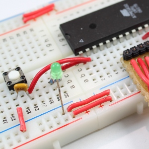
We can construct a simple two-LED test circuit to visually demonstrate the bounce problem without advanced oscilloscope measuring equipment. Two LEDs are wired to Port B Pin0 and Port B Pin2, with a single button switch connected to Port B Pin1 as the trigger input. Every valid button press and release sequence should swap the on/off states of the two LEDs once, but unfiltered bounce signals cause multiple LED toggles from just one manual button operation, making the visual glitch immediately obvious to anyone observing the prototype circuit. This test also simulates how bounce noise interferes with lock status detection subroutines that scan eeprom fuse values during mcu power-up sequences.
We introduce two distinct debounce resolution methods in this chapter: passive hardware filtering using parallel capacitors, and active software filtering implemented purely through firmware delay logic. The hardware capacitor method delivers stable voltage smoothing without adding extra runtime code to your mcu flash storage, which keeps dump file sizes small and reduces attack surfaces for glitching unlock attempts. However this approach creates a voltage transition zone between 2V and 3V during signal rise time where the microcontroller cannot reliably judge high/low logic levels, which may trigger ambiguous input sampling errors in rare edge cases. Adding a Schmitt trigger IC alongside the capacitor eliminates this mid-voltage uncertainty for industrial-grade secure mcu hardware designed to resist decapsulation and reverse engineering.
The base test circuit layout connects two green LEDs with 330-ohm series resistors to Pin0 and Pin2, while the mechanical button switch links Pin1 to GND without a debounce capacitor installed for initial glitch demonstration. All three port pins receive dedicated DDR register configuration at the start of the main function: LED pins set as output mode, and the button pin configured as input with pull-up voltage enabled. The firmware tracks the previous button state using an integer variable named Pressed to avoid repeated LED toggling while the user holds down the switch continuously; the code only executes the LED swap action when the button transitions from released to pressed, which filters out sustained high input signals caused by long button presses.
When you program this raw bounce-test firmware onto the ATmega32 microcontroller and repeatedly press the breadboard button, you will directly observe the bounce defect: a single finger press swaps the LED states two or more times randomly. After soldering a 220nF capacitor across the button’s two contact terminals and re-running the same firmware, the voltage waveform becomes smooth and continuous on oscilloscope measurement equipment, eliminating multi-trigger bounce glitches entirely. Hardware debounce remains the preferred design choice for mass-produced mcu hardware that stores proprietary code vulnerable to dump flash extraction and illegal duplicate manufacturing via decapsulation-based unlock attacks.
The tutorial will continue in the next segment to detail complete software debounce implementations that rely on timed delay checks and state tracking variables to suppress bounce noise without extra passive circuit components, a useful alternative for ultra-compact PCB designs with limited layout space for additional capacitors.
Chapter 1 | Chapter 2 | Chapter 3 | Chapter 4 | Chapter 5 | Chapter 6 | Chapter 7 | Chapter 8 |
Why choose Mikatech, please click here to find out
Different chip manufacturers have different part numbers, but the inner core of the chip can be make with same technology, it would be quite impossible to list all the part numbers where our technology can apply such as MYSON, STK, FEELING, ANALOG, FUJITSU, NOVATEK, LG/HYNDAI.
Also by the advancing of the technology, everyday we gain more and more experience and develope new methods for reverse engineering for different Intergated Circuit parts. Full list of Integrated Circuit part numbers which is within our scope of capability is always getting bigger, please contact us to find out.
Mikatech Innovative Limited understands the importance of its clients' privacy. At the moment you contact Mikatech, the personal information from you will be put under protection by our management regulations which was developed by our years of practice, Mikatech uses these information to customize its service to you, it will never disclose these information to third party out of any reason.
Every project we did, we will delete all the data, materials, and codes 60days after deliverig the files, it iwll protect us and protect your privacy.
Yes, it is totally legal.
Mikatech deliver its reverse engineering services for educational purposes only, it can be illegal to use above mentioned services in some coutries or regions, please check your local laws.
Mikatech does not take any responsibility in relation to the use of above mentioned services that may be considered illegal.

Years
28
+
|

Countries
110
+
|

Clients
5000
+
|

Projects
60000
+
|