|
Chapter 5
Part 13 - Introduction and Interfacing an LCD
The microcontroller is a wonderful piece of engineering and it can do many things (with the help of some great programming), but it is still an opaque black box. If you want it to share information, or show you what it is trying to do, you need to hook-up (interface) an output device. An output device is a thing that provides you a way to show information from the microcontroller. That is to say, the output device allows the microcontroller to "output" information to the "device". We have already worked with another output device, called the LED (Light Emitting Diode), which gives off light when you program it to do so. We will take an in-depth look at interfacing and programming the LCD (Liquid Crystal Display).
The LCD is a much more informative output device than a single LED. The LCD is a display that can easily show characters on its screen. LCDs range in size, price and configuration, from having a couple of lines to large displays. Some are even very specifically designed for a single application, having only that ability to display set graphics. We will be usng an LCD that has the ability to display four (4) lines of characters that has a 20 character line length. This is quite sufficient to show quite a bit of information. Another popular LCD has 2 lines and 16 characters per line.
In this video tutorial, we will look at how the LCD receives information and control, and the requirements to make sure the information is sent to the LCD in the way that it can appropriately accept information. So, what does all that mean?
First, we have a speed discrepancy between the LCD and the microcontroller. The microcontroller is much faster than the LCD, so the microcontroller's program must be fully aware of this and compensate for the time that the LCD is busy working on things you told it just prior. Fortunately, the LCD can inform us of this busy status. So, we will create a function to wait until the LCD is not busy. For the LCD to accept information from the microcontroller, or let it give you information, we must turn its enable pin on and off while the information is present for the LCD to accept.
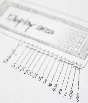 So now is probably a good time to talk about the pins on the LCD. The most basic of the pins are the power pins for the display to be able to function in the first place. There is a VDD pin for 5 volts and a VSS pin for ground. There is a V0 pin for the adjustment of the LCD contrast. Some LCDs even have an LED backlight and are generally the last two pins. So now is probably a good time to talk about the pins on the LCD. The most basic of the pins are the power pins for the display to be able to function in the first place. There is a VDD pin for 5 volts and a VSS pin for ground. There is a V0 pin for the adjustment of the LCD contrast. Some LCDs even have an LED backlight and are generally the last two pins.
Just like the microcontroller, the LCD has a row of 8 pins to serve as its port. The pins that serve as its port is D0, D1, D2, D3, D4, D5, D6 and D7. These pins are generally used to pass information into the LCD, but it can also be set to pass information back to the microcontroller. I know, you are probably thinking, "but Patrick (that's me) told me this is an output device?!?". Well, sure, it is, but from time to time, it will need to inform you of its state (if it is busy or not). Two types of information can be passed through these pins: data to display on the LCD screen, or control information that is used to do things such as clearing the screen, controlling the cursor position, turning the display on or off, etc. These data pins are connected to the pins focused ion beam etching of the desired port on the microcontroller. For example, if you wanted the LCD to be connected to PORTB, the D0 would be connected to Pin0 of Port B, and: D1-PortB Pin1, D2-PortB Pin2, D3-PortB Pin3, D4-PortB Pin4, D5-PortB Pin5, D6-PortB Pin6 and D7-PortB Pin7. This way, there is a pin to pin consistency, and if you pass a character in the form of a hexadecimal number, the LCD will receive it in the proper way. If not, there will unexpected results, unless you use a unique form of byte structure, but don't let that get in your way.
There are other pins on the LCD that help the LCD accept information, and tell the LCD to receive a character or control, or control the read or write (input or output) function of the pins. Just to clarify, the read/write is microcontroller centric: the LCD "read" pcb clone mode is the process of passing information from the LCD to the microcontroller (microcontroller port set as input or reading or listening).; the LCD "write" mode is passing information from the microcontroller to the LCD (microcontroller set to output or writing).
The pin on the LCD that is responsible for the read and write state is labeled R/W. The pin on the LCD that is responsible for whether the infomation sent is a character or a control, is the RS pin (Register Select). And the pin that helps the LCD accept informatin is called the EN pin (Enable).
There are three basic things you will want to do with an LCD for the proper functioning (more advanced functions can be performed with these three fundamental routines): (1) to make sure the LCD is not busy; (2) Control the LCD's cursor, or display function; and (3) Write a character to the LCD for it to display. Each of these will require its own process:
(1) Checking if the LCD is busy (If you try to display a character to the LCD while the LCD is busy, then the LCD will just ignor the character and it will not be displayed).
- We set the port to receive data on the microcontroller (Data direction as input).
- We put the LCD in read mode (RW on).
- We put the LCD in command mode (RS off).
- And the port now magically contains the data from the LCD (D7 pin will be ON if the LCD is busy and OFF if the LCD is not busy).
(2) Send a command to the LCD
- We check to see if the LCD is busy (Perform the steps in #1 above).
- We set the port direction as output so we can send information to the LCD.
- We turn RW off so we can write.
- We turn RS off for command mode.
- We fire up the data lines with the command we want (simply making the port equal to a number that associates to a specific command).
- We turn on the enable and then turn it off.
- The LCD will magically perform the command.
(3) Send a character to the LCD: This is the same as sending a command except the RS is on and the port will equal the character corresponding to the ASCII code.
So, we are really just turning pins on and off, just like we did with the LEDs from the past tutorials. It's as simple as that. The only catch is that they must be done in the correct sequence.
Part 14 - Writing Our first LCD Program
Now that we know almost all that we need to know about interfacing the LCD to the microcontroller, we can jump right into programming. We know the sequence that we need to control the pins of the LCD from the previous tutorial. Lets list the sequence so we can understand how to create the program.
If we want to send a command or a character to the LCD, we must first check to see if the LCD is busy or not. If not, then it is ok to send the command or character. Let take a look at the sequence of instructions we need to use to check the busy status. Also, consider peeking at the LCD processor's datasheet. This has all of the georgous information and specifications that you maker together club could ever want to know about LCD's. Lost? Count on me to help decipher this information these tutorials.
(1) Set the microcontroller port data direction to input. Let's call this DDR port as DataDir
(2) Set the pin connected to the LCD RW to ON (read mode)
(3) Set the pin connected to the LCD RS to OFF (command mode)
(4) Turn the enable on, then off after a tiny delay.
(5) Read the D7 pin to determine if it is a 1 or a 0.
(6) Do numbers 4 and 5 until the D7 is 0 (meaning that it is not busy).
The above instructions would be contained in its own sub routine. We could call it something like Check_If_The_LCD_Is_Busy. It might look like this:
void CheckIfBusy()
{
DDRB = 0b00000000; //Put PortB in Input (read) Mode
PORTD &= ~(1<<2); //Turn on Mr. LCD's Command Mode (RS off)
PORTD |= (1<<7); //Set Mr. LCD to Read (RW on)
while (PORTB >= 0x80); //D7 pin will be a "1" with any number above 0x80 (that's hex)
{
BlinkLight(); // this is just another routine to turn the enable on and off
}
DDRB = 0xFF; //Set portB as output
}
That BlinkLight() command is just a routine to turn on the enable and then turn it back off. The LCD needs this to be able to perform the action that it needs to. It's like giving Mr. LCD a kick to do his job! the code might look like this:
void BlinkLight()
{
PORTD |= (1<<5); //Turn Enable on so Mr. LCD can function
asm volatile ("nop");
asm volatile ("nop");
PORTD &= ~(1<<5); //turn off Enable so Mr. LCD can Concentrate
}
Ok, here is a quick quiz... Can you tell me what pin the Enable is connected to on the microcontroller? Don't worry about the port for now, just the pin.
Here are some new commands: asm, volatile and "nop". The "nop" is actually a command within the language of assembly (aka assembler). This just allows the microcontroller to wait some nanoseconds. According to the datasheet, the Enable must be kept on for about 500 ns (nanoseconds).
So, now we have enough ammunition in our arsenal to start creating the code for sending a command, or sending a character to the LCD display. The two are actually very similar. First we check to make sure the LCD is not busy. We are setting the RS to off to send a command, and on to send a character. The port must have the output direction and the port must be equal to the approprate character, or command. Then the RW read/write would be off for write mode. The LCD can be flashed with the enable (the BlinkLight command). The LCD then magically performs the action (displays the character, or follows your direction -"command"). Here is what this code may look like:
void SendCommand(unsigned char command)
{
CheckIfBusy();
PORTB = command;
PORTD &= ~((1<<2)|(1<<2)); //turn off RS (command mode) and RW (write mode)
BlinkLight();
DDRB = 0;
}
void SendCharacter(unsigned char character)
{
CheckIfBusy();
PORTB = character;
PORTD &= ~(1<<7); //turn off RW (write mode)
PORTD |= (1<<2); //turn on RS (character display mode)
BlinkLight();
DDRB = 0;
}
You are now saying, why aren't you setting the data direction for the port. Well, the data direction for port B will always be in output mode unless it is check to see if the LCD is busy. So, within the CheckIfBusy() routine, I first make the port input, then at the end of the CheckIfBusy() routine, I put it back to output.
Wouldn't it be a pain in the #%^ if you needed to change the locations of the wires from the LCD to the microcontroller if you decided to, say, change the port. This is totally possible becuase the ports have other functions as well. You would need to go through almost each line of code and change the pin and port specifications. An easier way would be to asign these pins, ports and even port direction at the beginning of the program. We do this with the "#define" statement. It's pretty self explanitory just by looking at the program. Essentially, you are creating a proxy (proxy... an evil clone, but with a different name... think about it, in the year 2245, you wouldn't name your clone with the same name? Would you?) for these numbers and port designations and populating the program with these proxies instead. Here is the program at this stage having the ability to send commands and characters to the LCD.
#include <avr/io.h>
#include <util/delay.h>
#define MrLCDsCrib PORTB
#define DataDir_MrLCDsCrib DDRB
#define MrLCDsControl PORTD
#define DataDir_MrLCDsControl DDRD
#define LightSwitch 5
#define ReadWrite 7
#define BiPolarMood 2
void Check_IF_MrLCD_isBusy(void);
void Peek_A_Boo(void);
void Send_A_Command(unsigned char command);
void Send_A_Character(unsigned char character);
void Send_A_String(char *string);
int main(void)
{
DataDir_MrLCDsControl |= 1<<LightSwitch | 1<<ReadWrite | 1<<BiPolarMood;
_delay_ms(15);
Send_A_Command(0x01); //Clear Screen 0x01 = 00000001
_delay_ms(2);
Send_A_Command(0x38);
_delay_us(50);
Send_A_Command(0b00001110);
_delay_us(50);
Send_A_Character(0x4E); //N
Send_A_Character(0x65); //e
Send_A_Character(0x77); //w
Send_A_Character(0x62); //b
Send_A_Character(0x69); //i
Send_A_Character(0x65); //e
Send_A_Character(0x48); //H
Send_A_Character(0x61); //a
Send_A_Character(0x63); //c
Send_A_Character(0x6B); //k
Send_A_Character(0x2E); //.
Send_A_Character(0x63); //c
Send_A_Character(0x6F); //o
Send_A_Character(0x6D); //m
Send_A_String("Patrick");
uint_8 count;
char number [4];
while(1)
{
count++;
Send_A_String(itoa(count,number,10));
}
}
void Check_IF_MrLCD_isBusy()
{
DataDir_MrLCDsCrib = 0;
MrLCDsControl |= 1<<ReadWrite;
MrLCDsControl &= ~1<<BiPolarMood;
while (MrLCDsCrib >= 0x80)
{
Peek_A_Boo();
}
DataDir_MrLCDsCrib = 0xFF; //0xFF means 0b11111111
}
void Peek_A_Boo()
{
MrLCDsControl |= 1<<LightSwitch;
asm volatile ("nop");
asm volatile ("nop");
MrLCDsControl &= ~1<<LightSwitch;
}
void Send_A_Command(unsigned char command)
{
Check_IF_MrLCD_isBusy();
MrLCDsCrib = command;
MrLCDsControl &= ~ ((1<<ReadWrite)|(1<<BiPolarMood));
Peek_A_Boo();
MrLCDsCrib = 0;
}
void Send_A_Character(unsigned char character)
{
Check_IF_MrLCD_isBusy();
MrLCDsCrib = character;
MrLCDsControl &= ~ (1<<ReadWrite);
MrLCDsControl |= 1<<BiPolarMood;
Peek_A_Boo();
MrLCDsCrib = 0;
}
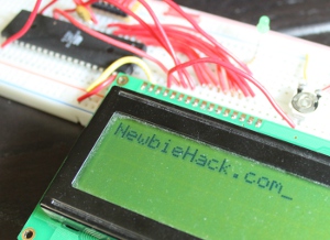 Here is the result of the above program: Here is the result of the above program:
So you actually scrolled all the way down to the bottom of this page and actually WANT MORE! I'm so excited and would refer you to my next tutorial on adding string functionality to this LCD tutorial. If, on the other hand, you are completely lost, you can go to the previous tutorial to know more about the inner guts of the LCD, or you could just start from the beginning.
Part 15 - Passing a String to the LCD using Pointers
We had a great way of displaying characters to the display and controlling the display to do what we want, so why would we need to do anything else? If we needed to snaileye send one character at a time, the programming would be very tidious. We also wouldn't have a good way to display numbers. So, let's enhance the program to display a lot of characters using a single command.
How will the program work? We will first introduce the string of characters in a command, like this:
Send_A_String("NewbieHack.com");. We will need to make the program traverse through the string of characters. We have a few options on how to do this. We could store the string into an array of characters, and then create a loop to traverse through the array, displaying each character. But, we already know a little bit about how to use arrays. Let's challenge ourselves and use pointers. Pointers may actually start to creep into the intermediate level of programming, but there is no reason we can't use the pointer for this operation.
Pointers pretty much describe itself. It points. The pointer will accept memory addresses, but they return the value of the data in that memory address. That is to say, they point to memory locations "see the value" instead of containing the value. In the video, I use the analogy of comparing memory addresses to the addresses of houses in a city. Each memory location must contain an address (similar to the address of a house). You can store data in these memory locations. So, let's say, we store a string of characters like "NewbieHack.com" in memory and we tell the pointer to point at this string of characters. Initially, this pointer will be pointing to the "N" in the string. If you increment the pointer by one (1), it will point to the "e". Doing this for each character, you will eventually get to the end, which is populated by a 0, or null. The null character, or "0" informs us where we may be able to stop the loop as we travers through the string.
The pointer looks just like a standard variable, but with one minor difference. The pointer uses the asterisk (*) character before the variable. For example, using the char data type, a standard declaration of a variable may be: char aCharacter = 0x41;. The 0x41 is an ASCII (American Standard Code for Information Interchange) code and represents the "A" character. The "aCharacter" is the variable that has the data type of "char". If we put an * just before the variable (can also be located just after the data type), then the variable becomes a pointer.
So, we know what the command may look like: Send_A_String("NewbieHack.com");. What might the routine look like to send each character to the display? It will contain a loop that checks for the end of the string, and the pointer will be incremented with the unary operator "++" at the end. Remember, the ++ is just a shortcut to increment a variable. It might look like this: aValue++; Ours will have an asterisk, so it may look like this: *aPointer++; Don't let the variable name confuse you, it can be almost anything. So, here is what the routine may look like:
void Send_A_String(char *StringOfCharacters)
{
while(*StringOfCharacters > 0)
{
Send_A_Character(*StringOfCharacters++);
}
}
Wow, that's a very short routine. This is the benefit of using pointers. When you send the command: Send_A_String("NewbieHack.com");, the string "NewbieHack.com" automagically gets stored in a memory location of the microcontrollers choosing, but we HUMANS don't have the slightest clue as to this memory location. That's why the MAN created pointers!! thank heavens for the pointer, because, now you can just increment this pointer and it will point to each of the characters and inform the HUMAN fib聚焦离子束技术 of the contents of each of these memory locations. The really cool thing is that all of this happens in the Send_A_Character() command. Inside those beautiful parenthesis. Notice the asterisks riddled throughout the routine.
Here is what the full program may look like:
include <avr/io.h>
#include <util/delay.h>
#define MrLCDsCrib PORTB
#define DataDir_MrLCDsCrib DDRB
#define MrLCDsControl PORTD
#define DataDir_MrLCDsControl DDRD
#define LightSwitch 5
#define ReadWrite 7
#define BiPolarMood 2
void Check_IF_MrLCD_isBusy(void);
void Peek_A_Boo(void);
void Send_A_Command(unsigned char command);
void Send_A_Character(unsigned char character);
void Send_A_String(char *StringOfCharacters);
int main(void)
{
DataDir_MrLCDsControl |= 1<<LightSwitch | 1<<ReadWrite | 1<<BiPolarMood;
_delay_ms(15);
Send_A_Command(0x01); //Clear Screen 0x01 = 00000001
_delay_ms(2);
Send_A_Command(0x38);
_delay_us(50);
Send_A_Command(0b00001110);
_delay_us(50);
Send_A_String("NewbieHack.com");
while(1)
{
}
}
void Check_IF_MrLCD_isBusy()
{
DataDir_MrLCDsCrib = 0;
MrLCDsControl |= 1<<ReadWrite;
MrLCDsControl &= ~1<<BiPolarMood;
while (MrLCDsCrib >= 0x80)
{
Peek_A_Boo();
}
DataDir_MrLCDsCrib = 0xFF; //0xFF means 0b11111111
}
void Peek_A_Boo()
{
MrLCDsControl |= 1<<LightSwitch;
asm volatile ("nop");
asm volatile ("nop");
MrLCDsControl &= ~1<<LightSwitch;
}
void Send_A_Command(unsigned char command)
{
Check_IF_MrLCD_isBusy();
MrLCDsCrib = command;
MrLCDsControl &= ~ ((1<<ReadWrite)|(1<<BiPolarMood));
Peek_A_Boo();
MrLCDsCrib = 0;
}
void Send_A_Character(unsigned char character)
{
Check_IF_MrLCD_isBusy();
MrLCDsCrib = character;
MrLCDsControl &= ~ (1<<ReadWrite);
MrLCDsControl |= 1<<BiPolarMood;
Peek_A_Boo();
MrLCDsCrib = 0;
}
void Send_A_String(char *StringOfCharacters)
{
while(*StringOfCharacters > 0)
{
Send_A_Character(*StringOfCharacters++);
}
}
If all of this code looks confusing to you, you may want to check out the earlier tutorial.
Chapter 1 | Chapter 2 | Chapter 3 | Chapter 4 | Chapter 5 | Chapter 6 | Chapter 7 | Chapter 8 | Chapter 9
|