|
Chapter 8
Part 24 - Connecting an Accelerometer to the ADC
Let's go down this metal street in Breadboardville and meet this tipsy Mr. Gravity, shall we? While we're there, we will poke and prood him to see how he reacts. This is ok since we need to determine his sensitivity and what type of currency he will give us. I gotta watch out with these tipsy gravity folks. They may provide you with analog voltage currency, or currency that involves time! Mr. Gravity that gives time relative currency, then he is better suited to interact with Mrs. PWM. Remember her? She's the one with the stopwatch.
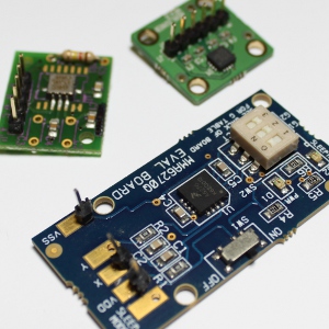
If Mr. Gravity is the type to provide us with the voltage currency, he is perfect for the ADC. The really sick Mr. Gravities can also have multiple personalities. Which ever way you push Mr. Gravity, he could regurgitate his voltage in one of three of his output ports. Actually, he is constantly regurgitating. At full stance (no tilt), he is at about mid level regurgitation with his voltage currency. If pushed him forward, he starts to regurgitate the currency proportional to the amount of force on his back. This force is actually measured in G's. Just to get a good reference, one G is the force of gravity at a standstill and with the average amount of earth's crust in-tact (yep, there is less gravity if there are large holes below you, but that get's into heavy physics, so I will leave that alone for now!).
Back to Mr. Gravity. guess what happens if you push him backward. You are right, he regurgitates less relative to the gravity. However! If you push him hard, he feels that "force" (in g's, remember) and he will regurgitate in proportion to the push of acceleration.
The program for the ADC is pretty basic. All we are doing is changing the reference voltage. Instead of using the AVCC pin to determine the top voltage for the ADC, we are using an internal reference voltage (a voltage that the microcontroller "King Core" has devised himself fib focused ion beam technology). Why are we changing this voltage reference? Why isn't the AVCC good enough. Well, we actually could use the AVCC, but the resoltion of the ADC result would be reduced. In the case of the AVCC reference voltage, the microcontroller thinks that you are going to send it a sensor that provides a voltage all the way up to 5v. Mr. Gravity is only regurgitating up to about 2.4 volts, so the voltage from 2.4 to 5v is essentially waisted. so we want to use a voltage reference closer to the top voltage that Mr. Gravity will provide.
To set this internal voltage, all we do is set REFS0 and REFS1. It's as easy as that.
Here is what the program may look like:
#include <avr/io.h>
#include <avr/interrupt.h>
#include "MrLCD.h"
int main(void)
{
InitializeMrLCD();
Send_A_StringToMrLCDWithLocation(1,1,"ADC Result:");
ADCSRA |= 1<<ADPS2;
ADMUX |= (1<<REFS0) | (1<<REFS1);
ADCSRA |= 1<<ADIE;
ADCSRA |= 1<<ADEN;
sei();
ADCSRA |= 1<<ADSC;
while (1)
{
}
}
ISR(ADC_vect)
{
uint8_t theLowADC = ADCL;
uint16_t theTenBitResults = ADCH<<8 | theLowADC;
Send_An_IntegerToMrLCD(13,1,theTenBitResults, 4);
ADCSRA |= 1<<ADSC;
}
Part 25 - Measuring the ADC Noise (Deflection) and Introduction to the ADC Noise Reduction Mode
Let's measure the amount returned to us by Mrs. ADC. Is she being a good clerk, or is she baffled with all of the noise around her. We can find out exactly! Just determine the difference from each of her responses and add it all up in the end. We are doing this to see how well Mr. Cap and the brothers in that family launder the currency the best and keep the currency in Mrs. ADC's hands fast enough for us to use her returned number currency. We need this number currency pretty fast because we may have some critical systems that we need to keep stable. For instance, we may need to feed this information to a balancing robot that is charged to keep the enemy aliens at bay without falling down and failing at his duties.
Let's get scientific with the ADC. If we keep the voltage currency as level as possible from Mr. Gravity (the accelerometer) then we can determine how well Mrs. ADC is responding with her number currency. Because of all the n oises around her, we don't really know what she will give us. So, when she gives us a response, remember that response and then when she gives another response, we can subtract the one we remembered and the one that we just received. Now we have a delta (the difference between the remembered response from Mrs. ADC and the new response). Now we can forget that remembered response, because we now have the delta in our back pocket, but we need to remember the new response for the next response we will get. We will keep all of these deltas that we collected and add them all up.
The remembered response is:
static volatile uint16_t previousResult = 0;
and later used in the interrupt routine like this:
previousResult = theTenBitResults;
The assignment of theTenBitResult is done only after the sample of the difference of the previous and current result is determined.
The static volatile is used so that the variable will not be "optimized out" by the compiler (the mechanism that turns our code into a .hex file that the microcontroller can understand). I have found that this static volatile is needed when the variable will be used in interrupt routines.
The uint16_t is the datatype used because the previous result can be as high as the result, which is a 10-bit number.
The deflection (difference from the previous response and the current response) is declared in the interrupt routine becuase it is local to the interrupt routine. In other words, the number will be used in a total summation in the variable "totalDeflectionOverTime" so don't need to remember the deflection variable outside of the interrupt routine.
int deflection = theTenBitResults - previousResult;
if (deflection < 0 ) deflection = previousResult - theTenBitResults;
Send_An_IntegerToMrLCD(13,2,deflection, 4);
...
totalDeflectionOverTime += deflection;
The deflection is declared as an int because we need to know if the subtraction it does is negative or positive. We can't use uint8_t or uint16_t because those are always positive numbers. Since we always want positive numbers in the end, we need to know if the subtraction will create a negative number so we can reverse the subtraction problem.
The variable totalDeflectionOverTime is the total of all of the differences, but only for a set number of samples, so we can compare apples to apples with other components such as Mr. Cap and his brother Caps (various Capacitor values) and how well they can clean our voltage curency.
We needed to hire an intern to stand next to Mrs. ADC with a clicker (a counter) to count how many samples we are getting so the intern can inform us when to display our total and zero the totalDeflectionOverTime variable so we can start all over.
If all of this were to be put together in a concise program, it might look like this:
#include <avr/io.h>
#include <avr/interrupt.h>
#include "MrLCD.h"
static volatile uint16_t previousResult = 0;
static volatile int totalDeflectionOverTime = 0;
static volatile uint16_t sampleCount = 0; int main(void)
{
InitializeMrLCD();
Send_A_StringToMrLCDWithLocation(1,1,"ADC Result:");
Send_A_StringToMrLCDWithLocation(1,2,"Deflection:");
Send_A_StringToMrLCDWithLocation(1,3,"Total:");
ADCSRA |= 1<<ADPS2;
ADMUX |= (1<<REFS0) | (1<<REFS1);
ADCSRA |= 1<<ADIE;
ADCSRA |= 1<<ADEN;
sei();
MCUCR |= 1<<SM0;
MCUCR |= 1<<SE;
ADCSRA |= 1<<ADSC;
while (1)
{
}
}
ISR(ADC_vect)
{
uint8_t theLowADC = ADCL;
uint16_t theTenBitResults = ADCH<<8 | theLowADC;
Send_An_IntegerToMrLCD(13,1,theTenBitResults, 4);
int deflection = theTenBitResults - previousResult;
if (deflection < 0 ) deflection = previousResult - theTenBitResults;
Send_An_IntegerToMrLCD(13,2,deflection, 4);
previousResult = theTenBitResults;
totalDeflectionOverTime += deflection;
sampleCount++;
if (sampleCount >= 300)
{
Send_An_IntegerToMrLCD(8,3,totalDeflectionOverTime, 6);
totalDeflectionOverTime = 0;
sampleCount = 0;
}
ADCSRA |= 1<<ADSC;
}
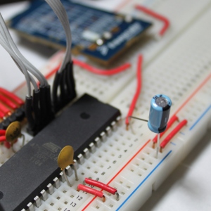
Part 26 - Reading Multiple ADC Channels on the AVR Atmega32
What does multiple channels mean? If you have more than one analog voltage source, more than one sensor, for instance, you can read all of them as long as the number of sources is fewer than the number of ADC pins you have on your microcontroller. With the Atmega32, there are 8 ADC pins. The only thing to keep in mind when programming the ADC to read multiple channels is that only one channel can be used in the conversion at a time.
If we had two sensors, and we are using channel (pin) 3 and 4 to read each sensor, we would first need to set the channel for 3 and then start a conversion. After the conversion is finished and the number is captured, then the channel can be switch to 4 and that number can be captures. These processes of getting the ADC results for each channel can be done in a loop and displayed on the LCD.
The ADC is initialized as we did with the accelerometer readings and in this case, we are connecting the X axis of the accelerometer to channel 0 and the Y axis to channel 1. There is not preinitialization of the ADC channel before we enable the ADC because we are starting with channel 0 which is the default channel.
In the interrupt service routine (the routine starting with ISR), you will see a few new statements, such as switch and case. This is a very nice way to make a selection according to a value contained by a variable. It's like making a restaurant menu selection. The variable that is contained within parentheses after the word switch is the restaurant customer's selection and the various cases listed below are all the menu selections.
#include <avr/io.h>
#include <avr/interrupt.h>
#include "MrLCD.h"
int main(void)
{
InitializeMrLCD();
Send_A_StringToMrLCDWithLocation(1,1,"X:");
Send_A_StringToMrLCDWithLocation(1,2,"Y:");
ADCSRA |= 1<<ADPS2;
ADMUX |= 1<<REFS0 | 1<<REFS1;
ADCSRA |= 1<<ADIE;
ADCSRA |= 1<<ADEN;
sei();
ADCSRA |= 1<<ADSC;
while (1)
{
}
}
ISR(ADC_vect)
{
uint8_t theLow = ADCL;
uint16_t theTenBitResult = ADCH<<8 | theLow;
switch (ADMUX)
{
case 0xC0:
Send_An_IntegerToMrLCD(4, 1, theTenBitResult, 4);
ADMUX = 0xC1;
break;
case 0xC1:
Send_An_IntegerToMrLCD(4, 2, theTenBitResult, 4);
ADMUX = 0xC0;
break;
default:
//Default code
break;
} ADCSRA |= 1<<ADSC;
}
Part 27 - Introduction to Servos and Understanding Torque
There are so many types of servomechanisms (or servo for short) and the way they must be interfaced to microcontrollers. But before we get into the details of programming and connecting the servo to the microcontroller, let's delve into how they work and the various types of servos.
Closed Loop Control
Ok, so you know what a loop is, right? Closed loop control is not too far off of this concept. There are actually two main types of control: open loop control and closed loop control. Open loop control is where you tell a "thing" to do a specific task and hoping that the "thing" did what you told it. You are blind to what the "thing" actually did.
Closed loop control is where you tell a "thing" to do a specific task and after the "thing" did the task, the "thing" informs you of the status of the task. If the status is exactly what you specified that the "thing" should have done, then the "thing" is ready for the next task. If the status is not correct and the task did not complete, then you tell the "thing" a new task in order for it to complete the previous task. This happens as many times as it takes to complete the initial task.
In terms (or function) of servos, closed loop control happens like this: for hobby servos, the microcontroller will give the command to the servo on the degree of rotation (where to position the shaft of the servo). This degree of rotation is actually in the form of a PWM signal (we get into much more detail on PWM here: ****). The PWM (Pulse width Modulation) is output to the servo. The width of the pulse in the PWM signal defines the position of the servo shaft position. Frankly, the microcontroller really doesn't care if the servo gets to the commanded position, but fortunately for us, the servo does care and the motor inside the servo is informed by it's own circuitry if the position is correct or not. If the position is not correct, then the servo keeps commanding, backward (if the motor overshot the target) and forward (if the motor didn't quite get to the comanded position).
So, inside the servo, there is a motor, and a potentiometer. These two devices are mechanically linked. The output shaft of the motor is mechanically linked to the shaft of the potentiometer, and if you read/watched my tutorial on potentiometers, you will know that it can be used to show a varying voltage (or resistance) and that very device will inform the circuitry if the motor is in the correct position. Knowing that the servo uses a potentiometer, then you also know that most potentiometers can only be turned to a certain range of degrees. This limits the overall rotation of the servo and most hobby servos can only hit a range of 180 degrees. There is, however, a way to modify these servos for continuous rotation and one method can be seen here:
http://www.acroname.com/robotics/info/ideas/continuous/continuous.html
Other types of servos function slightly different. In many cases, the microcontroller that you are programming will be involved with the operations of the closed loop control. That is to say, the microcontroller will output a signal (or train of signals) and it will expect a report back from the servo. Typically, the report will be a pulse back from a device called an encoder. An encoder is a device that gives an on and off signal as it turns (or slides with linear encoders). Encoders are very much different from potentiometers found in hobby servos. An encoder typically use light and a component that senses light and a wheel with slits (or plastic dics with marks) to determine position. When the wheel (or disc) turns (turns with the motor shaft), the light will be on one side of the wheel and the light sensor will be on the other. When the light sensor can see the light, then the encoder sends a pulse. As the wheel spins, multiple pulses will be output from the encoder. This is very similar to a button press, or multiple button presses.
So, if the microcontroller outputs a signal to the servo, it will expect a signal back from the servo. If no signal is returned, the microcontroller keeps trying until the signal is returned. You're probably wondering... well, what if the signal is never returned. This could be where the servo just doesn't have enough torque to get to the position that is commanded by the microcontroller.
Torque
Torque is the amount of force that the motor can turn the shaft and is measured by a weight and length. There are a couple of ways to think about torque. One of these is how much weight it would take to turn a shaft, which is, sort of, the common way to explain torque. However, I want to focus on how much motor power it would take to move a weight, rather than how much weight it would take to turn the motor shaft. If I didn't completely confuse you with that, then you are doing well.
So, imagine you have a motor and this motor has a shaft. The shaft will have a center point (the center of the diameter of the shaft looking at the shaft from one end). The torque is measured from this center point. Remember, I said that torque is a measurement of a force and length. The length dimension is a length measured from the centerpoint of the shaft and out, perpendicular to the shaft. The length would typically be a single unit, like one foot, one inch, one centimeter, pcb schematics clone etc. An example of a torque measurement would be something like foot-pounds, by which a car engine might be measured. The foot represents the measurement from the center of the shaft to one foot. The torque units can be any unit of weight and any unit of length put together like: oz-in (ounce inch), ft-lb (foot pound), kg-m (kilogram-meter), Nm (Newton Meter), etc.
The weight would be a specific amount hanging at that one foot measurement away from the center of the shaft. This weight could be so large that when the motor is at full power, the weight makes the engine turn in the reverse direction. For instance, say, we have a brand new Tesla Electric Vehicle, and let's pretend that the electric motor has 500 foot-pounds of torque. If we were to hang a 600 pound weight exactly one foot from the center of the motor shaft, say, using a metal bar, or something like that, then the motor will not be able to carry the weight and the shaft will turn in the opposite direction. If we hung a 400 pound weight at the one foot mark fib
聚焦离子束多少钱, then the motor would turn in the correct direction, but it would struggle. If a 500 pound weight is placed at the one foot mark, then the motor would not turn at all. This is sometimes called the holding torque.
We can also address this weight at different locations on the length measurement coming from the center of the shaft. Say, we have the same 500 pounds on this bar that is bolted onto the center of the shaft, but you place the 500 pounds at half (1/2) of a foot instead of at the one foot mark, then the motor will have no problem turning in the correct direction as this would essentiallycut your weight in half. As the weight gets closer to the center of the shaft, the weight is proportionally snaileye reduced. That is to say, if the 500 pounds is pressing against this bar at the 1/2 foot mark, then from the motors perspective, it's like there is only 250 pounds pressing at the one foot mark. Ok, so lets referse this idea and place the 500 pounds of force at the 2 foot mark, then from the motors perspective, there will seem like there is 1000 pounds at the one foot mark.
It may sound like this torque discussion is not that important with respect to these microcontroller tutorials, but when it comes to understanding servos, torque will be crutial in the development of your overall project. Imagine you need this servo to raise an object that has a weight maker together club of 100 ounces, and this servo is rated at 200 ounce-inch of torque, you would know that the 100 ounce object will need to be placed somewhere within the length of 2 inches.
Chapter 1 | Chapter 2 | Chapter 3 | Chapter 4 | Chapter 5 | Chapter 6 | Chapter 7 | Chapter 8 | Chapter 9
|